Incompetent Installers , incompetent regulation Do I need a MIM-B19N?

Hi Tim,Trystan,

The Pipes are now a Bus Backbone of 22 mm Copper pipes.

Each radiator is connected to the bus by 15 mm feeders.

Each Radiator has a TRV fitted.

The Network is protected by PRV’s fitted at both ends.

The Heat Pump is protected , and isolated from the Radiators by the Heat Exchanger.

I initially wanted my entire house heated by the Heat Pump, but that proving impossible, I have been reduced to heating my living room only.

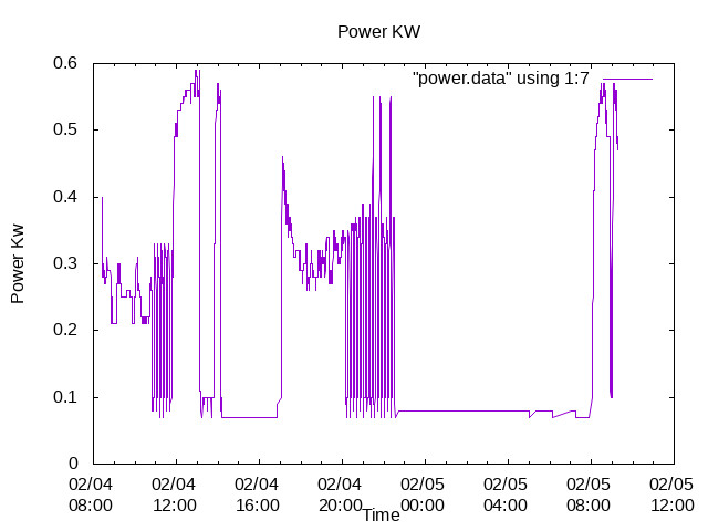
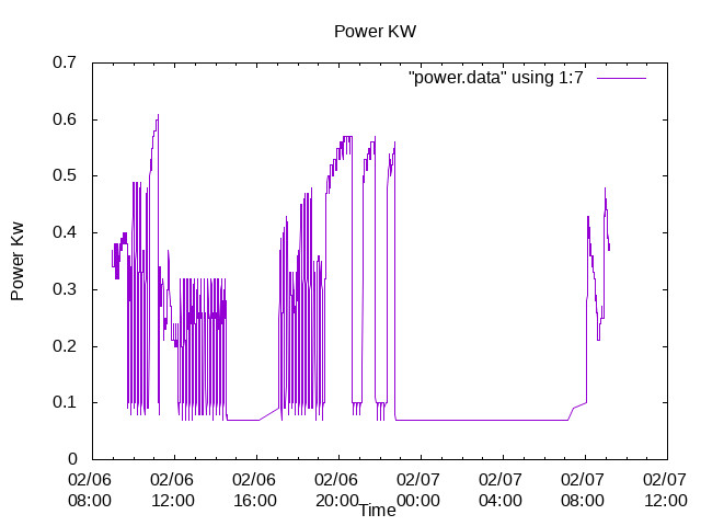
The System , as it stands, is not capable of heating my sole heated room , my Living room, during cold periods when the outside temperature is less than three degrees…

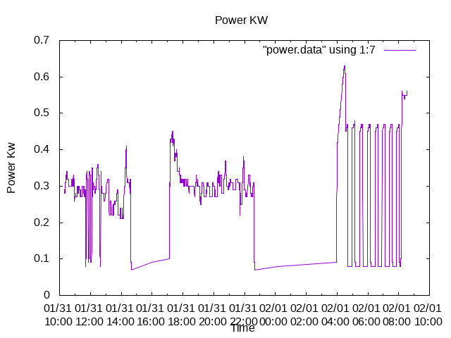
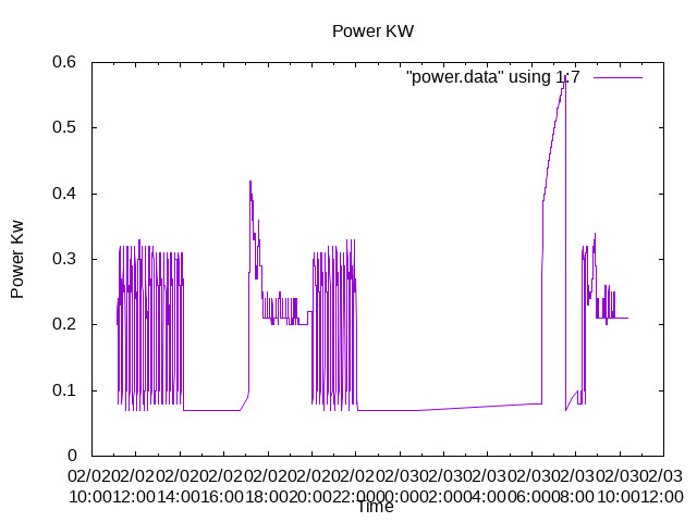
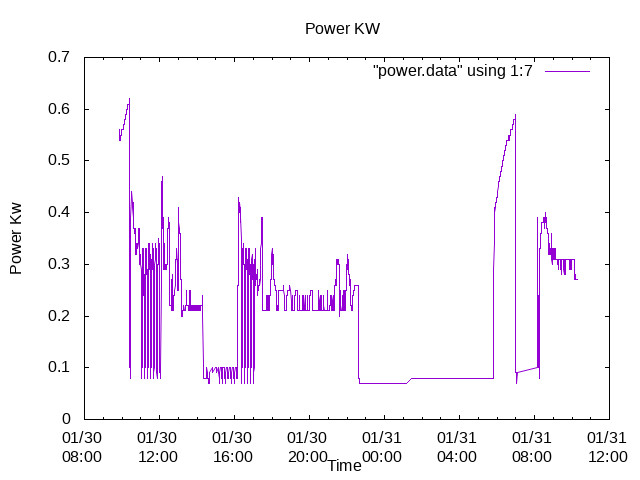
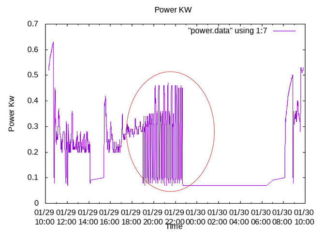
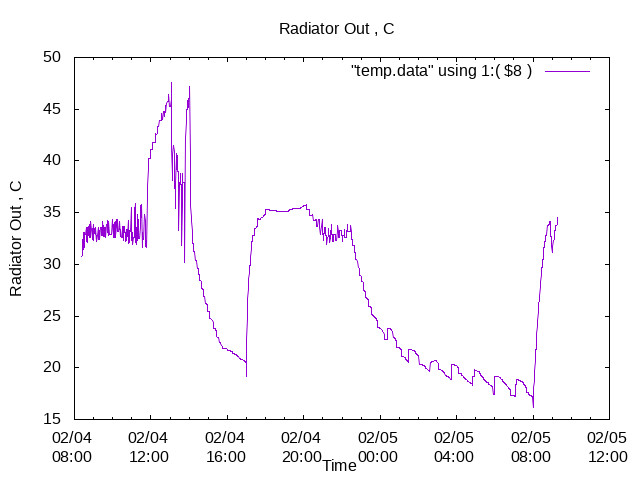
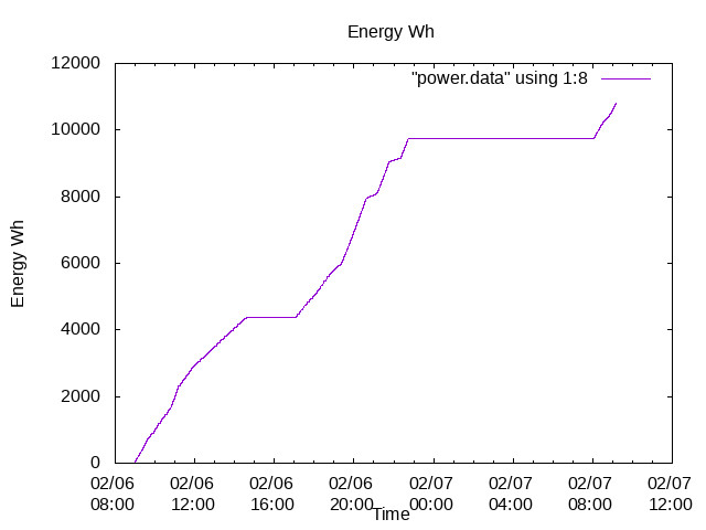
The Tank was fitted to remove the violent oscillations that occurred when the heat pump was operating at 25% of maximum power, as shown in the MCS documentation.

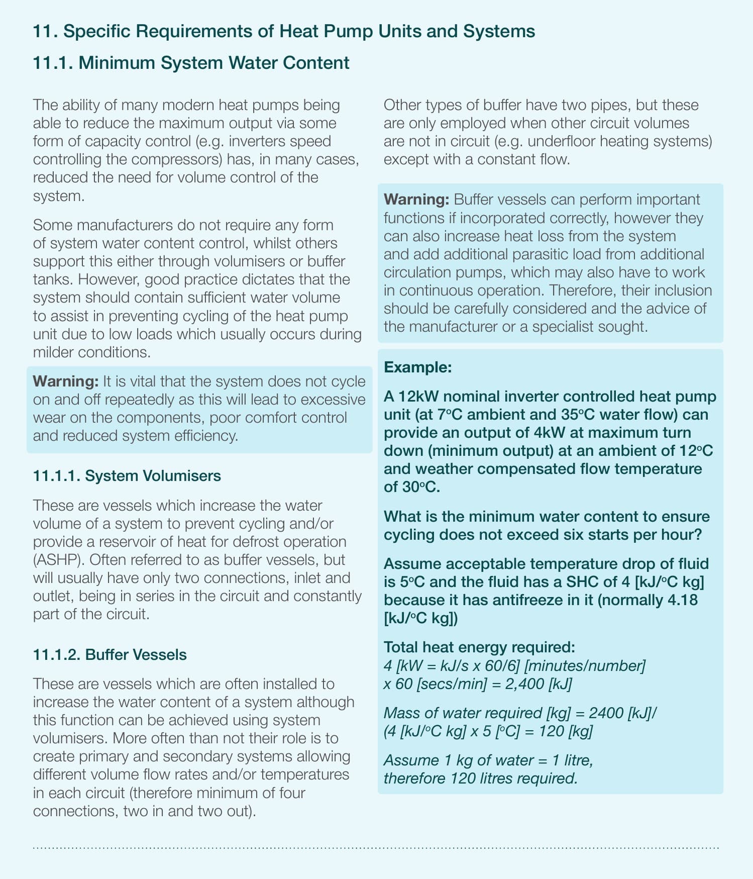
The Tank was also justified by Samsung in that the pipe volume on the primary side of the Heat Pump had only 6 litres. Samsung stipulate a minimum of 20 litres.

The Tank was also justified by Samsung in that it would prevent Winter Freezing.

My Then “installer” fitted the tank in parallel not understanding, why, or where, the tank was to be installed.

I know , it is a long story , but , for me a costly and painful exposure to the realities of Heat Pumps.

ian

1 Like

Hi Trystan,

I think I may have found one of my problems!

De-icing comes in two flavours, Electrical and Thermal, Both consume energy.

1 ) Electrical De-icing.
The Electrical de-icing is that tested by the Heat Pump Diagnostic t3.
The t3 diagnostic seems to be O.K , with the electrical consumption of circa 100 Wh, in agreement with Tim’s estimate.

  1. Thermal De-icing
    The Thermal energy appears to be is taken from the Hot Water tank, usually between 4 am and 8 am .
    If the Hot water tank does not contain enough energy the system calls the Heat PUmp to fill the Hot Water tank with energy.
    Some examples
    13110
    Notice the large call to heat the Hot Water between 5 am and 8 am.

2211
Notice the large call to heat the Hot Water between 6 am and 8 am.

1309
Notice the large call to heat the Hot Water between 6 am and 7 am.

If I am not mistaken the system appears to be trying to de-ice with Hot Water from the Hot Water tank.
The Hot Water tank having insufficient energy starts the heat pump to fill the Hot Water tank with energy.

If I disconnect the Hot Water system , when this demand is made the Hot Water at 4 am , the Hot Water is heated up to 65 C , and , goes out of control!

I will now switch off the Water Heating, again, and see what happens.

My Talk with Telford was another demonstration of buck passing.
Telford “fully appreciate my predicament” , saying that Samsung dictated the system design.

Telford ,However, “No longer have the design specifications or drawings for my Heat Pump , the Heat Pump being built in 2021, and therefore too old”.

I am , yet again, being driven into the conclusion that this industry is not fit for purpose,and is beyond regulation by the three " Charitable regulators" MCS, NIC and the RECC.

ian

Great, That sounds fine assuming a ~5kW heat demand?
Is sounds like you upgraded the radiators as well? so all new double panel K2 radiators I assume?

If you want to dig into this in more detail I would suggest doing your own heat loss calculation for your home and calculating if the radiators that you have installed are sufficient to heat the home at design temperature. I wrote up my own calculations here and here and created a web tool called heatlossjs to help make these calculations. It’s not the easiest process, it takes quite a bit of time to get all the numbers right. You may also find a presentation I did on our installation here useful https://www.youtube.com/watch?v=m2-_x0XZUSM.

Ideally it would be good to calculate your heat demand in the livingroom if rooms that share walls with the livingroom are unheated and then calculate what is the mean water temperature required for those remaining radiators in your living room. You my remember my post above that the flow temperature required is likely to be significantly higher - but that may be ok.

How many radiators do you have in the living room and what are their dimensions?


Defrosts and the hot water tank

Correct

Yes this is correct, Samsung heat pumps are configured from our experience to remove the heat from the hot water tank for defrosts.

Yes, a good way to mitigate this is to have set periods when the hot water is heated in more efficient batches. E.g have the hot water scheduled to run 2-4am and if required 1-2pm. This will ensure that you have plenty of hot water for your own use as well as for defrosts and that hot water is heated efficiently in a long batch run rather lots of smaller top ups.

Given that your hot water cylinder is used for defrosts, I can’t see how that will help.


Back to the buffer / volumiser

makes sense

Given that the hot water tank is used for defrosts, it doesn’t quite make sense that the volumiser on the space heating side would be used for this as well…

I think before going forward with that it would be worth doing a bit more investigation to see if you can understand exactly what is happening during the cycling circled below. Did you say that you still see this with the parallel buffer turned off / isolated with it’s isolating valves?

image

The heat pump runs stably for ~3.5 hours (3:30-7pm), before starting to cycle.

Did a TRV close down at this point reducing the load on the heat exchanger but before the thermostat stopped calling for heat?

Hi Trystan,

Many thanks for your patience, If only Telford, Samsung , MCS ,NIC and the RECC would show sufficient patience and interest I would not be in my present predicament.

My biggest concern was with the thermal runaway experienced when I switched the Water Heating OFF using control 3011.
13110

The violent Power and Energy pulses shown are clearly unacceptable.

To prove that the THERMAL RUN-AWAY is indeed caused by the De-icing system I will switch OFF the Hot Water system , again.

The system is Oscillating at with different Amplitudes and Frequencies reflecting different “causes”.

I will try to experiment to separate the “cause” of each type of oscillation.

The poor efficiency of the system may be “caused” by the De-icing system calling for Hot Water Heating at 4 am .

I can , and have, switched the "Volumising Tank in and out of service.

The oscillations change in frequency but are not eliminated, with or without, the Volumising tank.

I will , again , only change ONE variable at a time , changing the variable every two days, trying to eliminate multiple causal effects and the change in outside Temperature.

I will, later, take your excellent idea of switching the Hot Water system ON pre-emptively during the night.

I fear that the Heat Pump will respond with Additional Energy Consumption, reducing , yet again , efficiency.

This is turning into an “O level Science project” on the a\attribution of “cause”.

ian

:joy: heatpumps do make good science projects!

1 Like

Hi Trystan,

Heat Calculations

The Radiator and piping requirements for my house were “Calculated” by the three original Companies who quoted for the “installation”.

Two of the companies produced nearly identical Radiator and pipework designs.

The Third company ," forcefully disagreed " with the other two , asking for " larger Radiators to be fitted".

The First Two companies in turn , “disagreed” with the Third company., saying that their estimates were correct.

I “measured” the Room Conductance , Watt per Degree C , for the living room .

Livingroom.ods (15.2 KB)

The Conductance was measured by taking the outside Temperature , The room temperature and the Power consumption of my Electric Room heater using a simple Electrical consumption meter.

My Measurement of Room Conductance was 77 Watts per degree C.

With the outside temperature of 0 C and a room temperature of 21 C the Temperature difference would be 21 C.

The Power consumed by the room was therefore 21 X 77 = 1.6 Kw.

The Energy consumed over an 8 hour period would be 1.616 X 8 = 13 Kwh.

More than sufficient for the 5 Kw Samsung, .

at an outside temperature of -5 the Power increase to 16 kwh.

at an outside temperature of -8 the Power increase to 17.8 kwh.

The Heat Pump objects to any consumption greater than 21 kwh.

.ian

Sorry Trystan,

I am using “Linux”.
You may not be able to use ods files.

Here is my Conductance calculations on PDF.
Livingroom.pdf (16.4 KB)

Hope you can read it.

Again , many many thanks for your patience.

ian

Hi Trystan,

I think I may have found “installer” error no 24 !.

Looking at the “installers” estimates for the required Size of Radiator, the “installer” makes no provision for the Temperature Drop caused by the Heat Exchanger and the piping.

My “installer” installed the Samsung without any knowledge about the Heat Exchanger.

My “installer” designed the Radiators for a Maximum Flow Temperature of 50 C and a outside Minimum Temperature of -3.99 C.

A Radiator Water Temperature of 50 C has never been achieved…

The outside minimum temperature is about - -6 C … -8 C.

Again Trystan, You have exposed yet another error by my former “installer”.

What now?

ian

Ian,

I think one of your issues causing the cycling is the fact that you are only heating one room, with the remaining TRVs switched off. The heat pump wont be able to modulate low enough and this is causing the cycling when the room is up to temperature and the TRV starts closing.

Colin

Hi Colin,

My Samsung was initially very unstable , cycling repeatedly when the outside Temperature was 15 C.

The Cycling was then attributed to the Heat Pump operating , as you say , at the minimum , 25% power rating.

A 50 litre Volumising tank was installed to smooth out these Oscillations.

The Volumising tank probably smooths out the Radiator Temperature Cycling .

However , the Hot Water System is still Oscillating.

The Volumiser tank also consumes more Energy , and lowers the Efficiency .

The System is already inefficient with the “designer” having no knowledge of the Heat Exchanger.

The analogy between Water and electronics is Truly remarkable.

ian

Hi Trystan and Tim,

When using Weather Compensation my Samsung is using TWO Thermostats.

  1. The Room thermostat, a simple Honeywell Thermostat.

  2. the Electronic Water Law Thermostat using the Air Thermistor outside, on the outdoor unit.

To limit excessive energy consumption , The Room Thermostat is AND ed with the Weather Compensation Thermostat.

Any Thermostat is prone to excessive switching caused on approaching the set temperature.

Both of these Thermostats are therefore prone to this Noise .

The Samsung Water Law Thermostat has Variable Hysteresis to limit the effects of noise.

The Honeywell Room Thermostat has a fixed Hysteresis.

The Effects of this noise are shown in the following power Graph.
248
Notice the Oscillations when the room Temperature falls in response to a drop in demand.

The smaller amplitude Oscillations appear to be caused by the Pump motors

The larger appear to be calls for the outdoor compressor to Run and the Pump motors…

The system is prone to oscillations caused by the Switching "noise " on BOTH Thermostats.

To reduce the effects of this dual Thermostat noise i Could

  1. Switch OFF Weather compensation. This would decrease the efficiency by 7-10%.
    OR
  2. Get A Better Thermostat, with variable hysteresis ,noise filtering and Energy limitation.

One other graph shows the absolute Radiator Temperature
02040823

The Radiator Temperature is slightly higher than the Water Flow Temperature.

I will now look at the absolute Temperature of the Radiators themselves.

ian

.

Hi Trystan,

THE REAL COP

I am returning to my comments about the Real Efficiency measurement of Heat Pumps.

Currently , COP is defined as

           **COP =  Energy Generated/Energy Consumed in generation**

However ,Neither

** Energy Generated **
** NOR**
** Energy Consumed **

** includes ALL the energy used by the Heat Pump itself!**

Absolute Energy Generated should be

. Absolute Energy Generated = Energy Generated - Energy consumed by the Heat Pump Itself.

The COP presented does NOT include ALL of the energy used by the Heat Pump itself.

For, Example, The Heat Pump can enter de-icing using Heat from the Hot Water tank.

The Energy used to heat the Hot Water in the first place , for de-icing , is regarded as part of the load., and NOT used in the COP Calculation…

ian

Hi Trystan, Tim,

I have measured the Real COP and compared with the Standard definition of COP.

From my energy consumption Graph
248

I get the Energy Consumption to be 11 kwh for 4-5 Feb

From the Samsung Heat Pump I get a generated total of 29 Kwh.

The REAL COP is therefore

** REAL COP = 29/11 = 2.6 **

The Samsung computed COP with a consumption of 8.8 Kwh is

** SAMSUNG COP = 29/8.8 = 3.3**

The COP Presented by SAMSUNG is , at least Questionable ?

ian

What was the reason to not use the samsung display/controller itself? Can you relocate that to your living room? That may provide the most significant improvement over using the 3rd party thermostat.

It may not be included by the samsung calculation, im not sure, but it should be included in wider boundary calculations as you say. It is included on mine, so is all other heat pump related consumption e.g the central heating pump, diverter valve and indoor controller of my unit. I also include any top up from the immersion heater in my monthly/annual summary calculations.

Interesting yes questionable, but I’m actually surprised that it would over-estimate the COP. It turns out that for Glyn’s it actually under-estimates the COP significantly due to taking pipe surface temperature measurements of flow and return to calculate heat output. Did the heat pump come installed with a separate electricity meter from which you could read kwh readings? If not I would suggest installing a class 1 SDM120 modbus output electricity meter if you get the chance to do so in future.

Thanks I will take a closer look at this later.


Changing the topic a bit. I decided that if I was to really make sense of your setup and @thedawnbefore’s system which also has a heat exchanger, I needed to get my head around heat exchanger maths. The effectiveness NTU method is a particularly useful way to calculate temperature drops etc across a given heat exchanger. There’s a nice python library that can be used for heat exchanger calculations here that implements this method https://github.com/CalebBell/ht.

I’ve ported the calculation for a counterflow heat exchanger from this library into a little javascript web tool calculator that combines a heat pump, heat exchanger and radiator system. It calculates the system temperatures required to give a certain heat output from the radiator system (with all parameters adjustable). Here it is: https://openenergymonitor.org/heatexchanger/2.html

The code for this is all here: https://github.com/TrystanLea/heatexchanger

A couple of interesting results:

  • The COP penalty from introducing the heat exchanger is not as large as I would have thought, it appears to be around a 0.1-0.2 drop in COP. Maybe at most a 6% drop. This doesn’t take into account additional pumping electricity consumption from requiring two pumps but assuming low energy pumps the penalty for an additional 20W of pumping power is only a further 1% drop in COP, so maybe not that significant.

  • Varying the secondary flow rate on the heat exchanger has less effect on COP than I would have thought , which is probably the point! the heat exchanger allows for a greater range of conditions on the heat emitter side.

  • The variation of expected specific heat values (3800-4200) for the primary and secondary fluids have relatively little impact on the COP.

  • If you drive the same radiator system directly rather than through the heat exchanger at the same flow temperatures used to obtain a given heat output with the heat exchanger you can get ~20% more heat output (mean water temperature is higher). You can alternatively get a 20% boost in heat output by increasing the flow temperature and decreasing the COP by 0.1-0.2 as above.

Caveats are of course that this is theoretical steady state calculation. It doest take into account the buffer or cycling or anything that dynamically varies like that but hopefully an informative theoretical background on which to expand the science experiment! :slight_smile:

Hi Trystan,

Again , to yourself , and all the others , many thanks.

Trying to improve efficiency of my Heat Pump along with the several different oscillation frequencies takes my mind off the seemingly unending struggle to get someone to trust.

The Tank manufacturer has now said that he “does not have the drawings or the test performance for my Heat Pump”.

The Manufacturer now says that they “do not keep the drawings , specifications or test results for old Heat Pumps.”.

My "old Heat Pump was manufactured in 2021.

Whilst it is possible that the original drawings, Specifications and Test results were NOT kept, I feel it is unlikely, and far too convenient for the manufacturer .

The Manufacturer further denies any responsibility for the design , saying that Samsung Designed it , Talk to them. The manufacturer also says that “we recommend 50 litre buffers on all our units, but , talk to Samsung !”.

As we say in Scotland, “it wis’nae me it wis the Big boy doon the road”.


Returning to the specific problems I have with the Heat Pump I have found one of the Oscillations to have a period of 14 minutes. A fourteen minute corresponds to the period of the pump sequence used by field setting 2091, 2092 and 2093 option 4.

I have reset the 2091 and 2093 options to option 3 and reinstated the Volumising tank.

The results , so far are gratifying.
268

The 2091 option 4 was changed to 2091 option 3 at 1900 along with reinstating the Volumising tank at 1900.

As usual I will wait another day before changing another variable.

The Energy for the same period is
268

Again , notice the excessive amount of energy used during the oscillations.

The Heat was supplied with TWO Electricity consumption meters, never fitted by my then “installer”.

These meters were amongst the other five major components missing from the original “installation”.

I have used my home made , and, so far as I can see accurate Consumption meter using an Arduino attached to a CT transformer.

I will however, have to install a Calibrated consumption meter on BOTH the Outdoor unit and the indoor unit.

ian

Hi Trystan,

One of many problems with the Heat Pump is the provision of an adequate Thermostat.

None of the Thermostats I have seen have

  1. Hysteresis control.
  2. Noise filtering.

I have been considering making my own Thermostat with inputs from

  1. A room Thermistor
  2. An outside thermistor to allow for weather compensation.
  3. A CT Transformer to reduce the Temperature when the Heat Pump has consumed a maximum amount energy.

The Output would be a relay connected to the B22,B23 Thermostat inputs on my Samsung.

ian

Hi Trystan,

A Real COP

Returning to my original suggestion for a redefinition of COP , could I suggest

Real COP = Total usable energy per day / Total Energy consumed per day.

with
Total Daily Available Usable energy that available to the end user…

and

Total Daily Energy consumed including all consumed by the Heat Pump itself.

The energy consumed would be measured by a calibrated Energy Meter.

The Energy available would be

Daily Energy Available = Output Water Temperature ( C) x Output Flow rate (l/sec) X Specific heat of Water.x 24x60x60.

With Hot Water accounted as that Energy consumed by the Heat Pump itself.

A Kwh meter input, a Water Temperature and Flow meter out.

ian

Hi Trystan,

Real COP ?

In Comparing my use of a Gas boiler last year with my Heat Pump this year , I have come to the conclusion that while the Heat Pump is undoubtedly more efficient than the Gas Boiler, the Heat Pump is continuously feeding energy into the HOT Water tank , whereas the Gas Hot Water was only used intermittently for less than 10 minutes each day.

So, the Heat Pump wins for efficiency but consumes much more energy in Water Heating than the Gas Boiler.

The Difference in the Definition of efficiency between the Heat Pump and the Gas boiler is critical.

The REAL COP.

So, I need to switch OFF the Water Heater on the Heat Pimp.

However, the Heat Pump uses the Energy stored within the Hot Water tank to De-icing.

When switched OFF , Field bit 3011 OFF, the Heat pump still calls for Hot Water from the Hot Water tank.

The Hot water tank is then filled with heat but runs completely out of Control sitting at a Water Temperature of 65 C.

Question?

How do I switch the Hot Water tank OFF and still have Hot Water for De-icing?

ian

There is standard for comparing the different system boundaries of heat pump seasonal performance factors (SPF’s). This digram from the Energy Saving Trust report illustrates this quite well

The boundary you are talking about is one further still, which is measuring the heat output from the hot water tank, they define that as the overall system efficiency:

The detailed analysis report is quite informative on these different boundaries https://assets.publishing.service.gov.uk/government/uploads/system/uploads/attachment_data/file/225825/analysis_data_second_phase_est_heat_pump_field_trials.pdf

Defining which boundary we are talking about is something we need to get better at in terms of our heat pump monitoring activities here.

Talking to Glyn again about this it seems that I was mistaken and his heat pump does take heat from the space heating system for defrosts if that’s what the heat pump was doing before going into defrost. It takes heat from whatever it was doing before the defrost.

There is a separate anti-freeze function that is different from defrosts, apparently that just runs the pump for a few minutes and that does pull heat from the cylinder but only if the pipes get below a certain temperature threshold. There’s probably a way of disabling the hot water cylinder but Im not sure how that’s done with a Samsung. Probably a question for Samsung technical support?

1 Like

Hi Trystan,

Where did you get this knowledge about Heat Pumps?

Who stimulated your interest and expertise? A schoolteacher, or a lecturer ?


The Hot water system on the Samsung is controlled by setting the lowest acceptable Hot Water Temperature. I have now set this to 25 C .

The highest possible Hot Water temperature has now been set to 48 C.

I have selected Hysteresis for the Hot Water Thermostat operating between the Lowest and Highest possible temperatures.

Hopefully this should greatly reduce Heat Pump energy consumption while still allowing the de-icing to operate.

The Volumising tank has been correctly fitted to the input Heat Exchanger ports for removing oscillations.

However, the Volumising tank should have been fitted to the input to the Hot Water coil for de-icing!


My next move will involve some plumbing !

ian