What’s the capacity of your heat pump and diameter of the pipes? Your annual consumption figures sound like a 5kW heat pump and heat loss? but Im not sure if that’s correct/established? I’d expect 22mm primary pipework at 5kW, I think Samsung may even recommend 28mm for part of the primary pipework even down to 5kW, but 22mm should be plenty (mine is all 22mm primaries for a 5kW heat pump, radiator connections all T off with 15mm pipes, all copper).
I would try contacting Samsung directly. I know Mitsubishi will send an engineer out if there is a suspected equipment fault (I dont think this is charged for - but I may be wrong about that).
Both of these issues sound like either control setting, circulation pump control or temperature sensor issues. A samsung engineer should be able to get to the bottom of the right configuration for your system.
Could you clarify as well your radiator TRV settings? How do you use the radiator TRV’s? are they all off apart from used rooms? or all on a low level e.g 1-2 or all on max? How many radiators do you have and what kind are they? single or double panel? If you do have time could you list all the radiators in your house, with dimensions and type and how you use those radiators e.g TRV off, TRV 1-2 / max etc?
Hi Tristan and Tim,
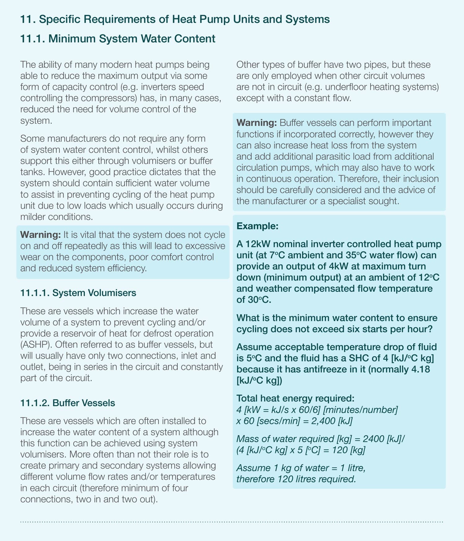
Have a look at the excellent text from the MCS about Volumising tanks.
What is your pipe volume ?
Does your system Oscillate, if so, what is the Amplitude and period of the Oscillations?
Can I see examples from other users about Cycling or Oscillations on the power or the Flow Water Temperature ?
Can you keep a database of examples of Cycling ?
Currently, I have switched out the Volumising tank on my Samsung.
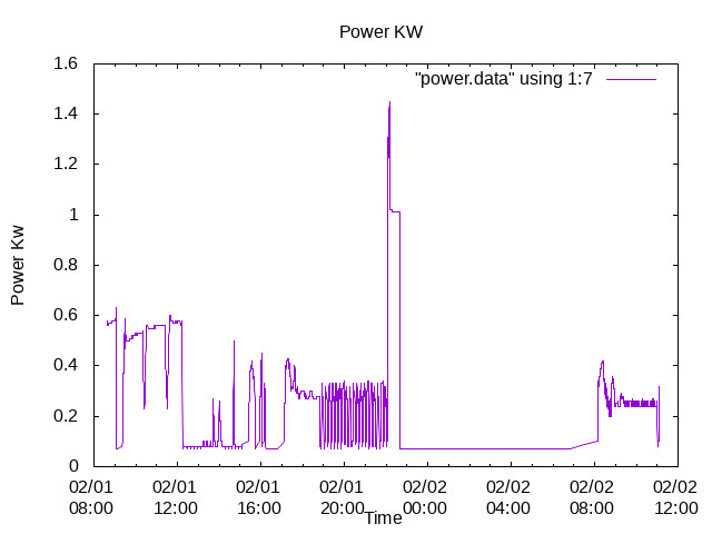
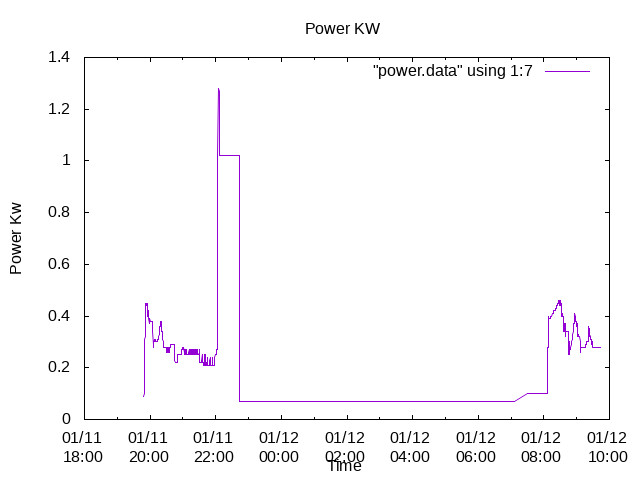
The power shows the Oscillations in Power during the evening of 1 Feb .
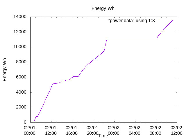
The Energy on 1 Feb shows the energy consumed during these oscillations.
My Volumising tank was switched off , the Period of the Oscillations therefore shows the effect of a circa 6 litre pipe volume .
Does anyone else see this behaviour?
I will now try again and change one variable each day.
Now I will put the 50 LTR Volumising taking the volume to 56 Litres.
ian
Trystan and Tim?
My Volumising tank was installed in parallel across the Flow and return of the Heat Pump out after the Three way valve!
this parallel fitting of the Volumising tank is supported by Kensa
How do I pipe up a buffer tank?
 You must install the buffer tank between the flow and return of the heating system only.
The flow is the first tee connection after the 3 port diverter valve. The return from the buffer must be the last tee into the heating return before it joins the return from the cylinder.
The MCS however says that the Buffer should be fitted in SERIES !.
Where should the Volumiser be fitted into my system?
Should volumising tanks be fitted in SERIES or in Parallel across the Heat Pump Output and return?
ian
On our HP, the DHW and Heating have two settings to control when the pump starts and stops. So there is a temperature differential, i.e. when to start and a stop temperature difference. On the DHW side of ours this is set to 0 but it’s set to 2 for the Heating, so when heating the pump will overrun the set point by 2 degrees. Does the Samsung have similar settings and if so could this be the reason for the overrun?
The other reason as @TrystanLea pointed out could be a sensor issue. We had this problem initially. The sensor for the DHW had a bad connection, so the HP was getting a bad reading. The sensors for ours are PT1000s, so any additional resistance from a bad connection gives a false reading.
What was happening due to this, was that the HP thought the DHW wasn’t up to the set point, so kept running until it reached it’s maximum which is around 65 degrees, throw an error, stop for a while and then repeat.
Simon
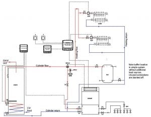
I cant quite see that picture clearly but that’s likely a system without a heat exchanger. It is indeed normal for a buffer or low loss header to be installed in parallel in systems without heat exchangers. The buffer is effectively providing the equivalent (hydraulic separation) function as the heat exchanger is on your system. To have both seems strange to me…? a volumiser in series with the heat exchanger would make sense as it would reduce cycling in the event that the secondary side of the heat exchanger is not loaded. You should however seek advice of a professional heating engineer, Im just an enthusiast householder really when it comes to heating system design giving my 2 cents from what I’ve learnt so far.
Hi Ian,
The Samsung config and documentation is VERY confusing. It might as well be in Latin. I have been extremely careful when changing those settings. You may want to share ALL the settings within that section for DHW. I can compare with mine.
William
Here is what my Samsung 16kW - via a massive external heat exchanger with the Indirect Hot Water Tank - does
Hi Trystan and Tim,
My Heat Exchanger was fitted by Telford the Hot water tank maker “to isolate the Heat Pump from Pressure and flow rate changes on the Radiators”.
My Volumising tank was calculated for size by Samsung and installed by my then “Installer”.
When my “installer” arrived to install the volumiser they did not know where to install the Volumising tank, the “designer” having been fired four weeks before!
The “installer” was shown both the Kensa and the MCS documentation , finally positioning the Buffer "between point after the 3 way valve and the Flow return, as per Kensa…
If seeking to smooth the power supply on an Amplifier, a 10000 Uf capacitor would be fitted across the power supply.
The 10000 uf capacitor would consume, and store, more energy.
The Buffer is consuming , and storing , more energy!.
ian
Correct, that is what we mean by hydraulic separation. A heat exchanger is typically fitted to allow glycol to be used in the primary circuit for freeze protection and water only (+inhibitor or other protection) in the secondary water that goes around your radiators. I’ve just given Telford technical a quick call and they dont seem to understand either why the buffer is in parallel and agree that a series connection would make more sense (they dont typically install a buffer or volumiser alongside a heat exchanger - at least with more recent samsung models where defrost energy is extracted from the hot water cylinder rather than the space heating system).
I think the buffer is only one factor of several that need looking at with your system. The controls and what is happening on the radiator side may be of greater importance… I asked about your radiators above, could you clarify what you are doing on the radiator side?
Hi William,
I also have been appalled at the quality of the Samsung Documentation.
I suspect that the original engineering documentation was written in Korean.
The Korean engineering source was then translated for a different audience , field engineers.
The File engineering version was then translated into English , Polish , German ,French,Dutch by engineers who had never seen the heat pump they were writing about!.
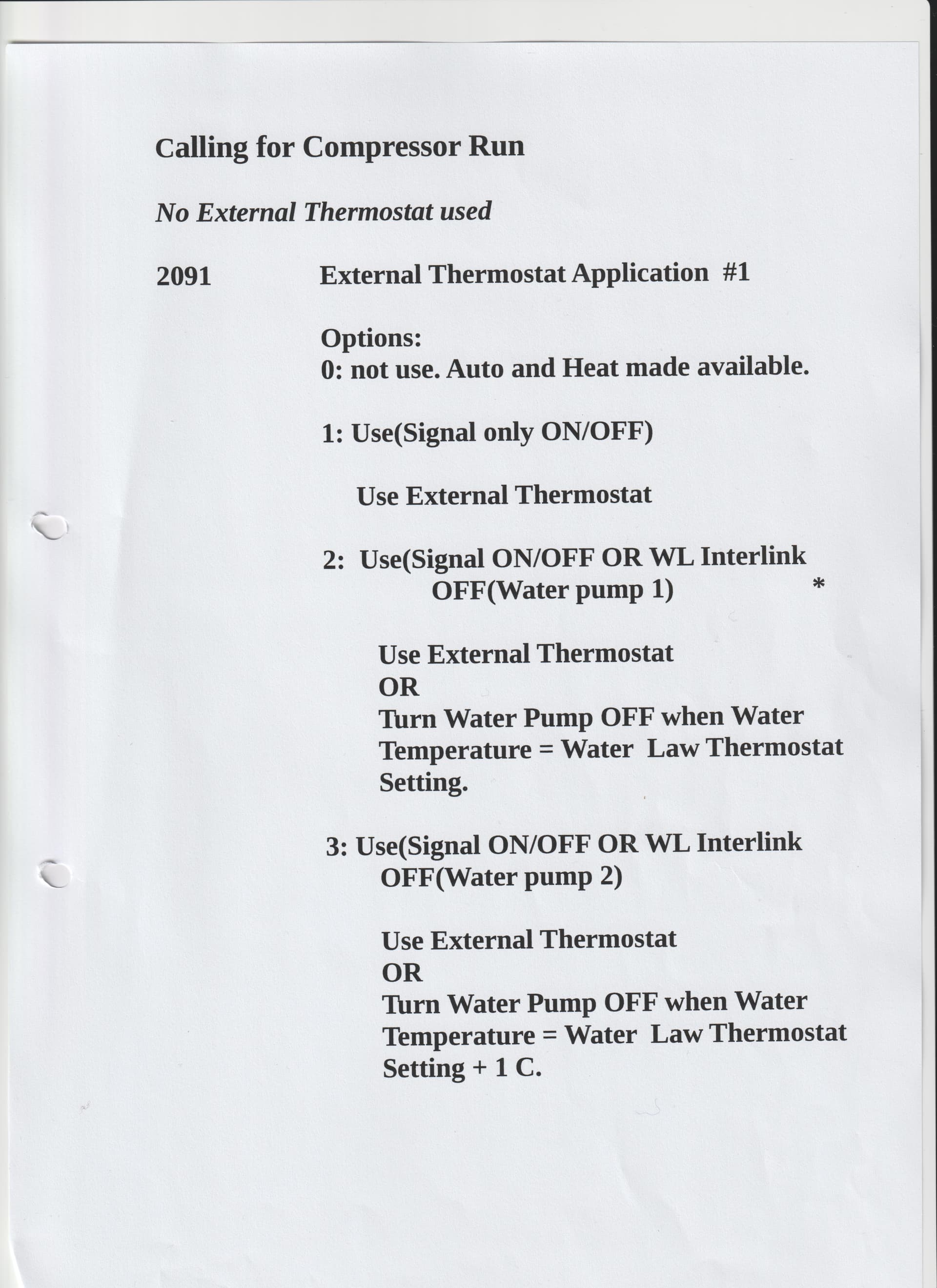
Specifically , “I think” that this is the meaning of the Field controls 2091, 2092 and 2093.
2091
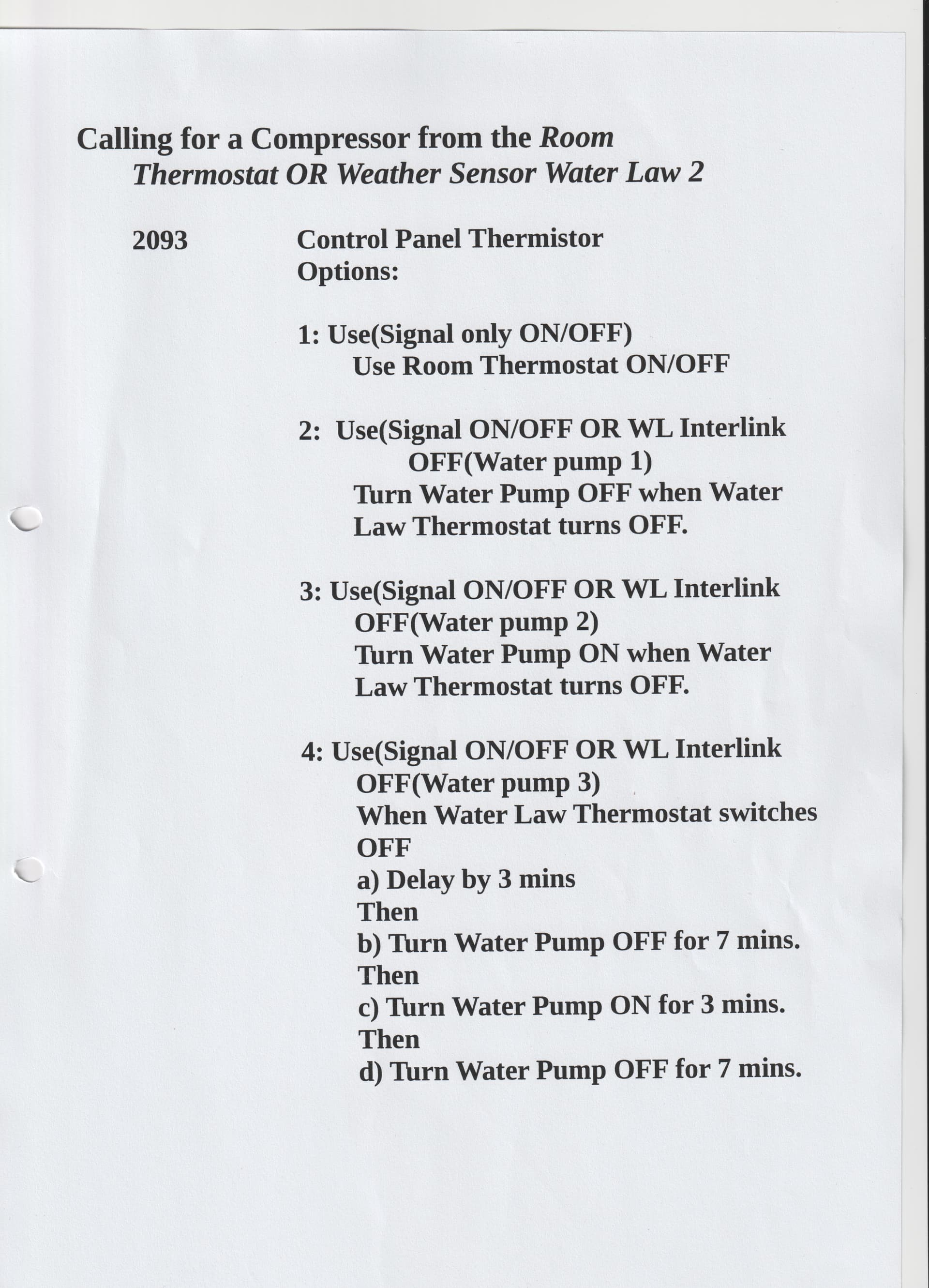
2093
With 2091/2092 the field engineer can
-
Use the Water law ( WL interlink) , Weather Compensation front Screen with 2091 options 2,3 or 4.
-
Select variable Water Law thermostat Hysteresis with
a) No Hysteresis using option 2.
b) Hysteresis = 1 C using option 3.
c) Hysteresis = 2 C using option 4.
£) Select How the motors are used following the Water Law Thermostat triggering.
a) Turn the Motors OFF when the Water Law Thermostat is triggered.2091 option 2.
b)Turn the Motors OFF when the Water Law Thermostat is triggered.at + 1C Hysteresis.2091 option 3
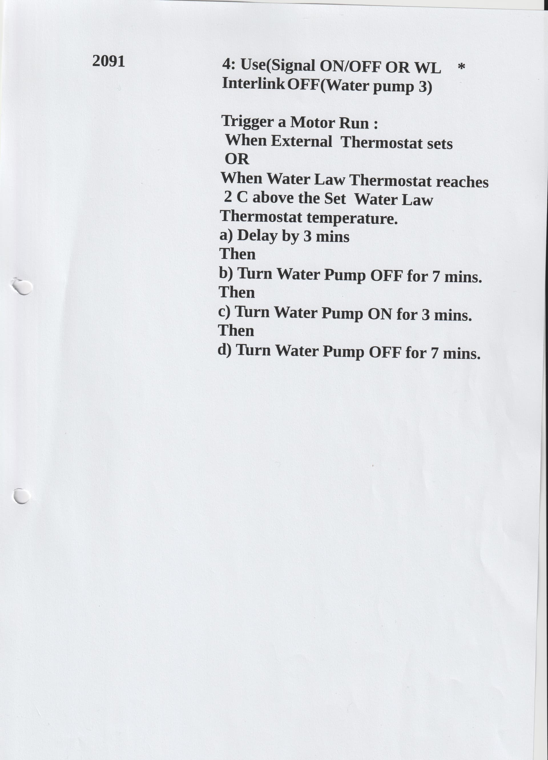
c) When the Water Law Thermostat triggers with 2091 option 4
Turn the Motors ON for three minutes
then
1) Turn the Motors OFF for a further 7 minutes
2)Turn the Motors ON for a further 3 minutes
3)Turn the Motors ON for a further 7 minutes
I have use 2091 option 4 providing
- The Water Law Thermostat Offset Screen .
- an Thermostat Hysteresis of 2 C.
- motor driven power pulses to the Radiators.on thermostat triggering.
With 2091/2092 OFF and only 2093 used Weather compensation is NOT used.
The Front screen is without the +/- % C Weather compensation control.
I am probably wrong about some of this , but the operation seems to conform my understanding.
ian
Hi William ,
My Samsung Field settings, 2091 2092 and 2093 !
I have removed all the spelling mistakes this time.
I have removed my original attempted translations of the Samsung Instructions.
Writing about this control system is difficult., I am beginning to appreciate the Technical Author’s problems.
The Samsung 2091,2092 and 2093 Field controls in Depth
The Samsung is here using TWO Thermostats, the Room Temperature Thermostat and the Water Law Thermostat.
The Water Law Thermostat has three different settings for Hysteresis.
The output controls TWO Sub systems,
- Calling the outdoor unit to heat the FLOW Water.
- Starting and stopping the motors.
In practice the system Calls the OUTDOOR unit to heat the Flow water when
- The Room Thermostat is below the required ROOM Temperature setting
AND - The Water Law thermostat is below the required Flow Water Temperature.
When called, the Outdoor unit heats up the Flow water to the required Water Temperature.
On reaching the Required Water flow temperature the Outdoor unit will stop providing heat.
The Required Water Law Flow Temperature is derived from the Straight line graph set by Field bits 201,202 and 203 plus the +/- 5 C Water Law offset from the Water Law Front screen.
Hope this clears up matters, I have , now much greater respect for the Technical Authors.
With 2091/2092 the field engineer can
-
Use the Water law ( WL interlink) , Weather Compensation front Screen with 2091 options 2,3 or 4.
-
Select variable Water Law thermostat Hysteresis with
a) No Hysteresis using option 2.
b) Hysteresis = 1 C using option 3.
c) Hysteresis = 2 C using option 4. -
Select How the motors are used following the Water Law Thermostat triggering.
a) Turn the Motors OFF when the Water Law Thermostat is triggered.2091 option 2.
b)Turn the Motors OFF when the Water Law Thermostat is triggered.at + 1C Hysteresis.2091 option 3
c) When the Water Law Thermostat triggers using 2091 with option 4
The Motors ON for three minutes
then
1) The Motors are turned OFF for a further 7 minutes
2) The Motors are turned ON for a further 3 minutes
3) The Motors are turned OFF for a further 7 minutes
The Motor control varies the amount of power , Heat supplied to the Radiators when the Water Law Thermostat triggers OFF on traversing the lower Hysteresis level.
I have use 2091 option 4 providing
1) The Water Law Thermostat Offset Screen .
2) Water Law Thermostat with a Hysteresis of 2 C.
3) A triple motor driven power pulse to the Radiators.on thermostat triggering.
With 2091/2092 OFF and only 2093 used, Weather compensation is NOT used.
The Front screen is without the +/- 5 C Weather compensation control.
Hope You have arrived her with a wee bit of understanding.
ian
Hi William,
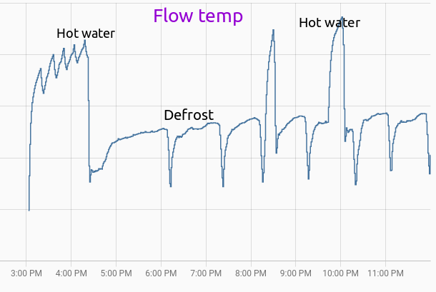
Thanks for the Graphs . I now know that my Samsung is Cycling or oscillating .
Have a look at these preliminary sketches of the "2091,2092 and 2093 controls on Samsung Heat pumps.
Flow_1.pdf (16.9 KB)
Water-Law_control .pdf (18.4 KB)
It May , I hope, clarify what is a difficult subject.
You say that you have a large Heat Exchanger , could I ask why?
I am still mystifier as to why , Telford, my tank maker, insisted on both a heat exchanger and a volumising tank.
Samsung later insisted on the volumising tank without explanation.
ian
Hi Trystan,
My nightmare continues!
**Telford , on system design **
I have again contacted Telford Technical department who have , again , passed the buck back to Samsung, saying that “the design of the system is up to Samsung.”.
**Samsung , Statement from Samsung on the Volumising / Buffer **
Looking at the system setup on you have been left with, the mechanical side of the system will need to be altered to allow the heat pump to be able to complete its defrost cycle, currently there is not enough water volume in the heating primary side to allow the heat pump to complete its defrost cycle.
The pipework setup around the cylinder will need to be re-designed to work with a small buffer / low loss header and the secondary side water volume of the radiator circuits, to allow the heat pump to complete its defrost cycle in the winter months.
After eight months of this endless shifting of responsibility , surely somebody can say
- "Do I need a volumiser/Buffer "
- if I Do need a Volumiser , How big a buffer? Telford originally recommended a 50 Ltr tank.
- Should the buffer be fitted in parallel ( Kensa’s recommendation) with the Heat Pump Water flow outlets ?
OR - Should the buffer be fitted in Series ( Telford’s recommendation ) with the Heat Pump water outlet?
Does anybody know what they are doing with these Heat Pumps?
A NOW , very sceptical Ian
Hi Trystan,
Many thanks for your patience!
MY Heat Pump is continuing to Oscillate,Vigorously!
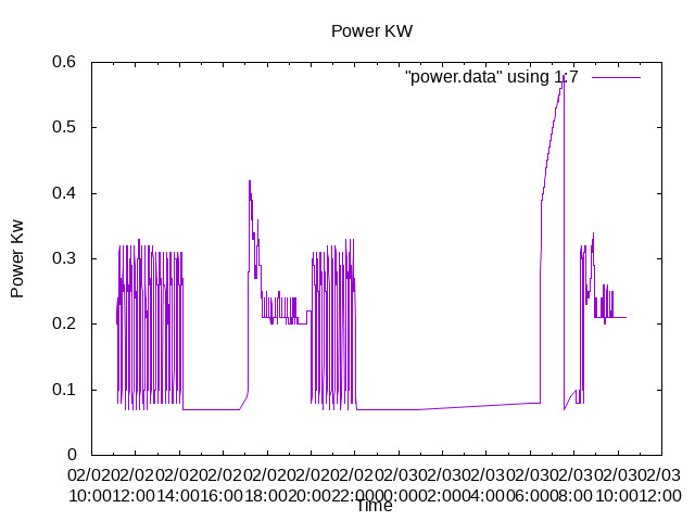
The Energy consumption shows the Hot Water tank starting at 6 am until eight am.
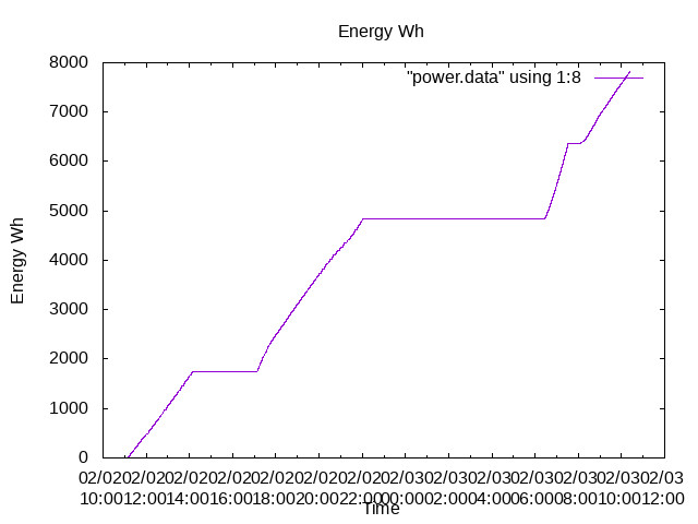
The Absolute Temperature Graph shows the Hot Water again starting at 6 am.
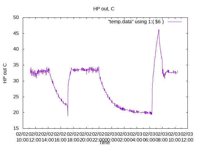
Conclusions?
- The Volumising tank does not inhibit some of the oscillations.
- The Hot water Tank sometimes consumes Large quantities of energy Energy despite being switched OFF with Field bit 3011.
- The probable Heat Pump Real Efficiency,
Real_Efficiency = ((output Power)(/Energy Consumed))*100 = 200 %.
ian
Sounds like progress but a bit vague.
-
The Kensa recommendation is as far as I can tell for a parallel buffer without a heat exchanger. The buffer is providing the same function as your heat exchanger is now (hydraulic seperation). It sounds like Samsung may be proposing removing the heat exchanger and replacing it with a low loss header - which would be the same configuration as you see in the Kensa diagram - not what you have now.
-
The Telford recommendation for a series buffer with your existing heat exchanger could also work, it should ensure sufficient volume for defrosts in your primary pipework. Your existing parallel buffer would be moved to a series orientation I assume. You are always going to have a performance penalty with a heat exchanger due to the temperature drop across it. If you have a low loss header instead and the flow rates either side are balanced (important caveat) your performance drop will be less.
-
You havent really answered my question about the radiators and pipework, from what I’ve read so far Im of the impression that you would like to be able to zone / turn off radiators in unused rooms and that the pipework diameter may be on the small side… The other configuration that does not require a buffer in parallel, low loss header or heat exchanger is an open circuit system but you do really need to ensure your system is designed correctly and that sufficient radiators are left open and the pipework size is correct for this configuration to be both safe and work efficiently. This is the configuration that I have and several others getting good performance, a bypass valve and series buffer can help mitigate the risk of all the radiators being turned off in the open circuit configuration.
Can you get Samsung to visit and organise a repair? as well as to review your control settings?
Hi Trystan,
The Quote from Samsung was the first recommendation ( Sept 22 ) for a tank to be fitted to the then system with the Heat Exchanger.
I understand , now, what has happened.
I have received several different reasons for fitting a Buffer tank, a ,Volumising tank, and a Heat Exchanger.
The Kensa Recommendations were for a Buffer to "protect the Heat Pump from the Pressure and Flow rate changes.
Unfortunately , the Heat Exchanger was fitted "to protect the Heat Pump from the Pressure and Flow rate changes.
So, the Heat exchanger was fitted to do exactly the same job as the Buffer.
A 50 Litre Volumising tank was what was required to protect the system from Cycling at a 25% power level. ( MCS 's description ).
So, the question comes down to a semantic difference between a Volumising tank , the MCS and my installers description , and a Buffer tank ( Kensa’s description )
So , the difference between a Volumising tank and a Buffer tank is one of is it to be a tank fitted in series or in Parallel with the Heat Pump flow output and returns.?
So do I risk changing the tank from parallel to serial ?
What difference would it make to change from a parallel to a series tank?
I do not think that the change from Serial fitted tank to parallel fitted tank will affect the large instabilities in this system.
Your question about the pipes raises yet another thorny question about the Radiator and pipe network.
The “installer”, along with the other two companies who quoted , demanded the removal of the original microbore piping with radiators , the Gas boiler and the Gas supply.
This cost £4200 before the “installer” appeared on the scene.
What a shambles.!
Many thanks,
ian
Ian, can you tell us what the answer is to the question about the pipes and radiators?
It would really help us all to understand how your systems works.