I am trying to create a home energy monitor using my ESP32 and the SCT013 [50A/1V] CT sensor (It gives a reading of 1v when 50 amps of current goes through a wire).
The readings I got was not accurate at all. They are off by a huge margin. Even if I do not clamp my CT sensor to any wire, it still gives me some sort of reading (between 1.5 to 2.0) and not 0. also when i clamp the it to the wire there is no changes at all.
I don’t have any sort of engineering experience and am pretty lost here. I just did whatever the guide told me to do.
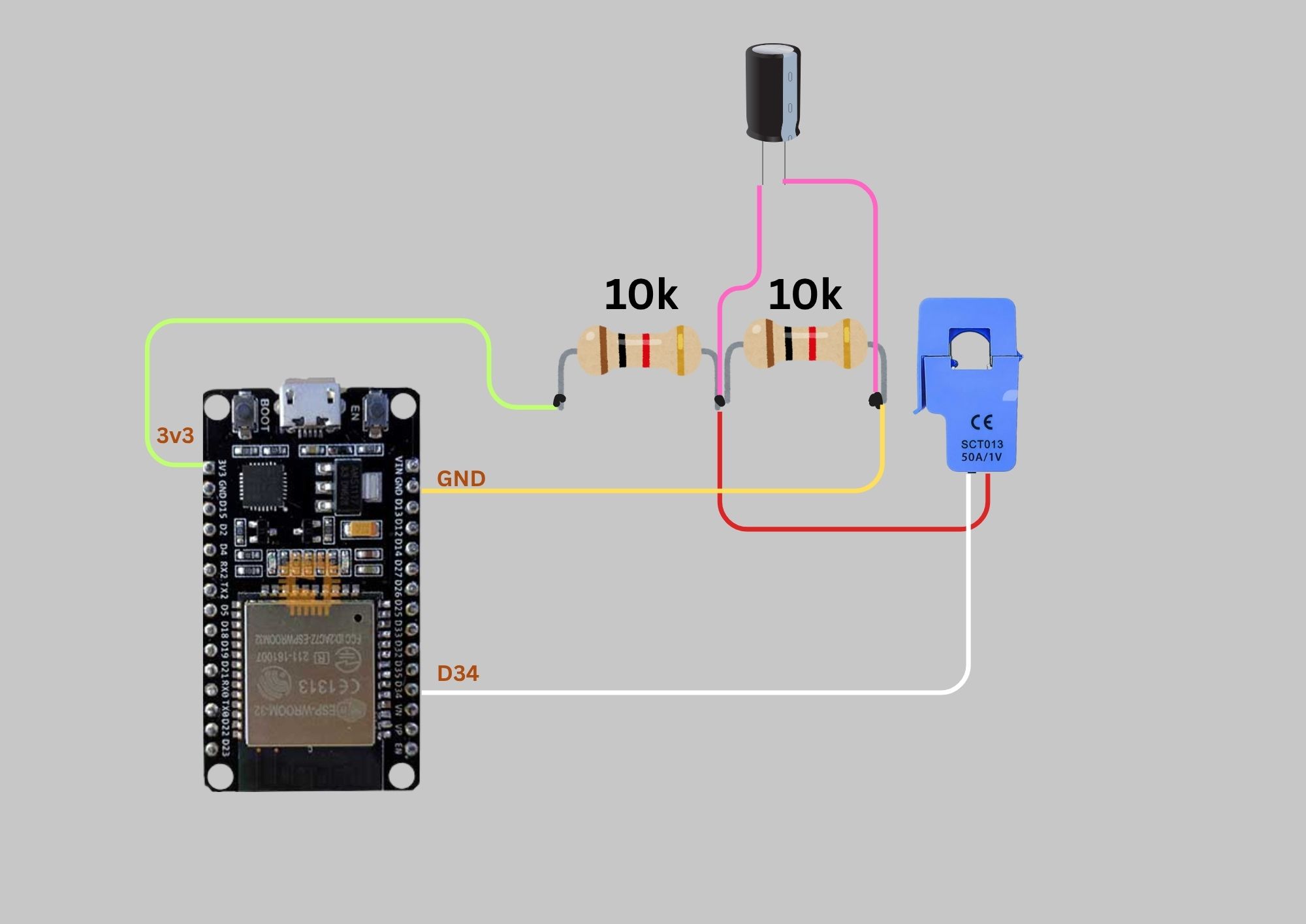
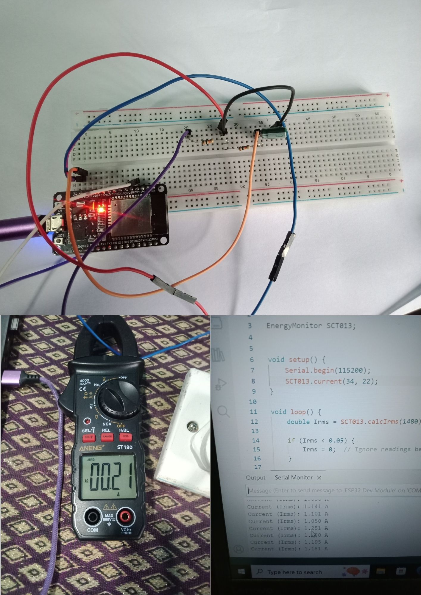
I have attached the circuit diagram I used and the code I uploaded to the esp32. Any help would be appreciated.
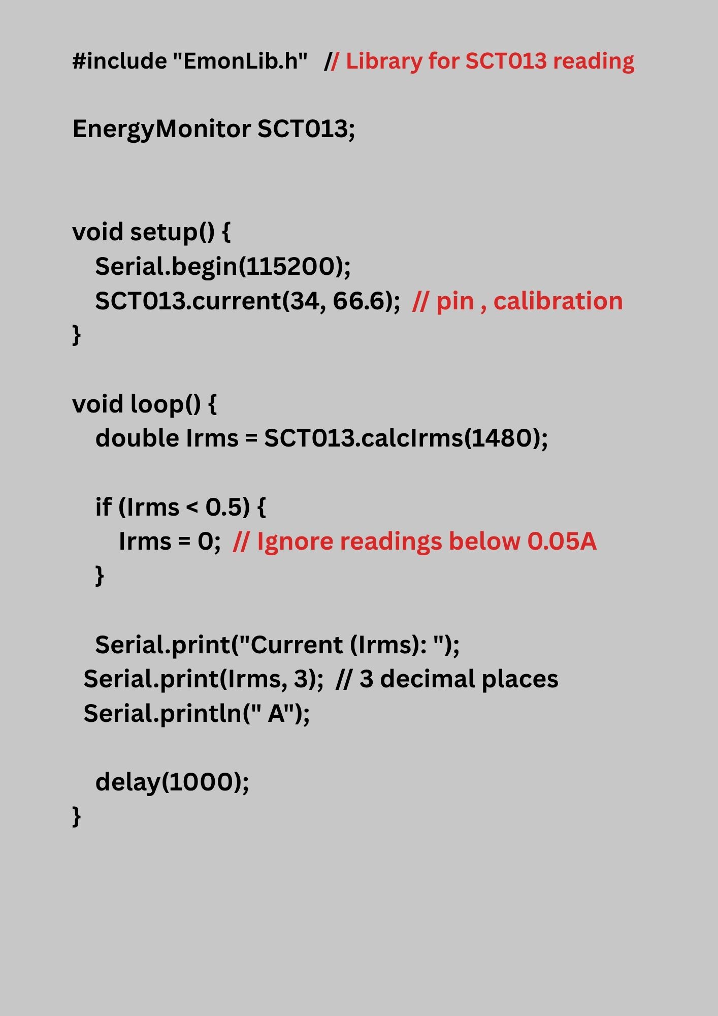
Source Code:
#include “EmonLib.h” // Library for SCT013 reading
I cut the SCT current sensor wire and there are 3 different wires are come from the sensor. Red, white and silver are there. I choose the white wire as signal and silver as ground. Also i attaché the circuit here,
No, there are not 3 wires, there are two wires and a screen. You must use the red and white wires to connect to your ESP32, you may connect the screen to ground, or leave it not connected (it is not connected inside the SCT013-050). Your picture showing red and white wires connected is correct.
tells me that the two 10 kΩ resistors between 3.3 V and GND are wrong.
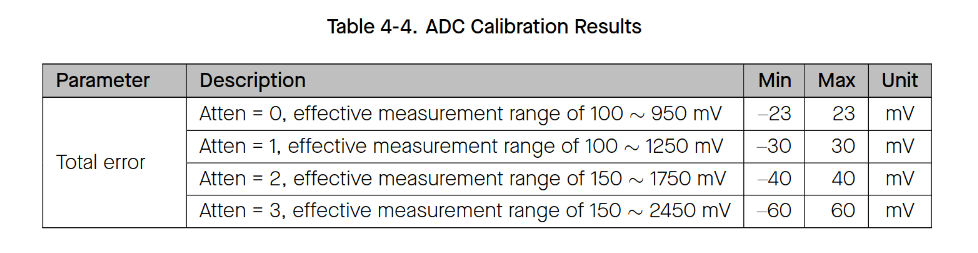
The voltage at the junction of the two must be different, depending on how you set the value of Atten in your code. It must be midway between the two voltages that define the measurement range.
If you have a 1 V rms output from your c.t., the signal swings between 1.42 V and -1.42 V, giving a total swing of about 2.84 V. This is more than the maximum your ESP32 can measure (2.3 V), so you cannot measure more than 50 × 2.3 ÷ 2.84 = 40 A accurately.
Therefore you must use your ESP32 with the setting Atten = 3 and you must change the two resistors to give a voltage of 1.3 V where they join (the red wire). Keep the resistor between red & GND (10 kΩ) and change the resistor between 3.3V & red to 15 kΩ.
If you must be able to measure up to 50 A, then you must connect another resistor between red and white wires from your c.t. The value of this should be 150 Ω. This changes the calibration of your c.t, so you will need to measure the current with another a.c. ammeter (as close as possible to but less than 5 A) and adjust the “66.6” number in the code to give the same reading from your ESP32.
I have never used an ESP32, I do not have one so unfortunately, I cannot test this for you.
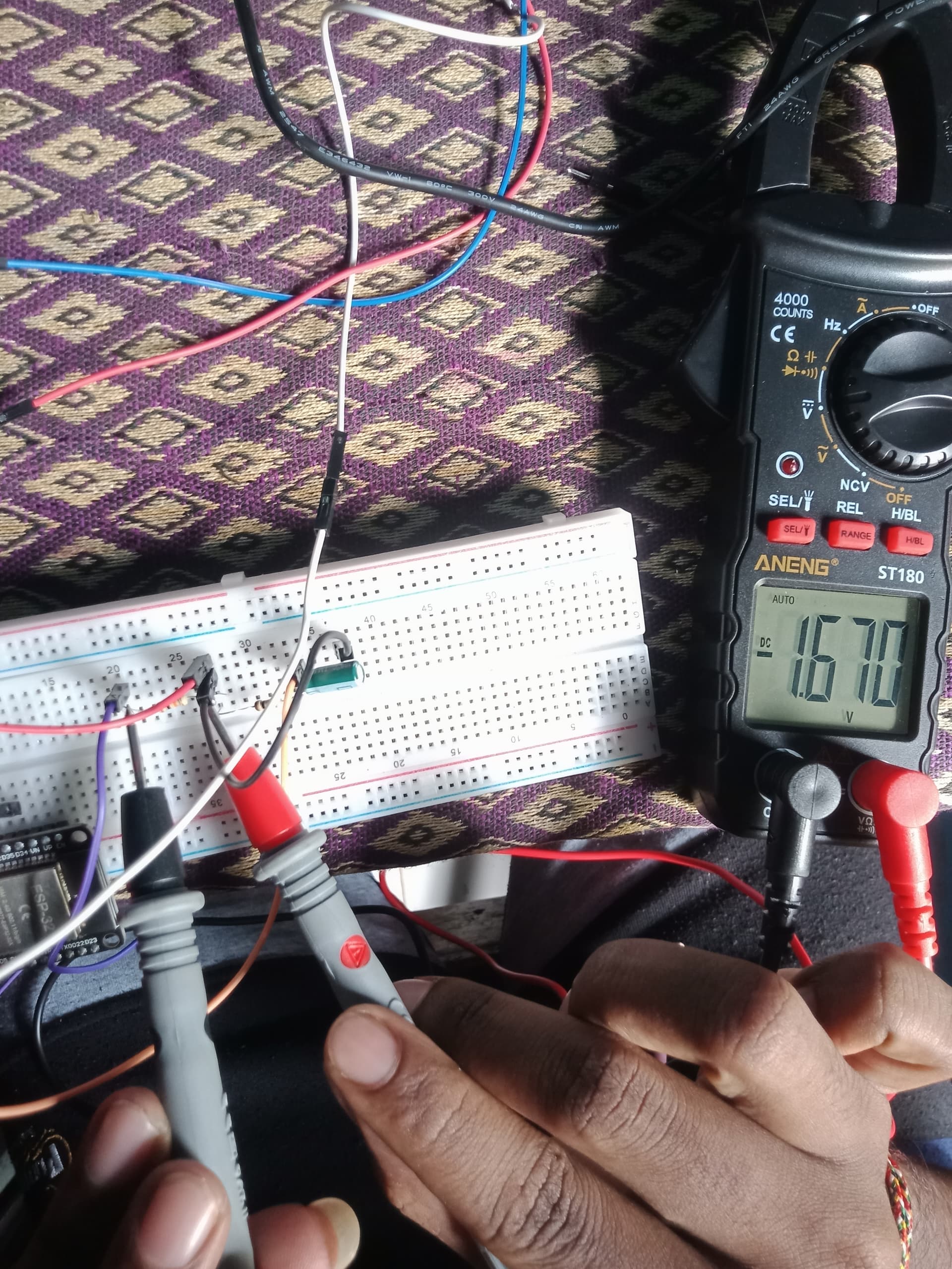
I connect the circuit according to your thought (Current sensor’s red wire to middle of both resistors, white wire to D34 of esp module, screen wire to GND in esp.) . It shows 1.65V between the first resistor and 1.65V between another resistor.
In this case there are no changes in reading. This means it shows some value without clamp in wire. Also, it shows the same value when I clamp in the wire. I attach the evidence here.
Read again my first reply to you. Whichever range (Atten = 0 etc) you are using, 1.65 V from GND to the red wire is not the centre of the measuring range. This is the first problem you must correct.
When you have corrected the voltage so that the red wire is at about 1.3 V, can you temporarily connect red and white wires together, and report the number you get by putting this line somewhere inside loop
It should be a number near to 1590 and in theory, it should be the same every time (every 1 second), but in the real world you can expect it to vary maybe 20 either side.
If it varies a lot more than this, the first thing you should do is make all those connecting wires as short as possible. Having long loops of wire is not good.
What are you using to power the ESP32? If there is electrical noise on that supply, then that will be appearing on your output.
Sorry, but I do not have an ESP32, and I have never used one. I have told you what I think you must do to get it to work, but it is clearly not enough. I don’t think I can help you any more.
Have you read all the topics here that mention the ESP32? You might find something which will help you. Here are a few:
This man used a separate ADC to make the analogue readings: