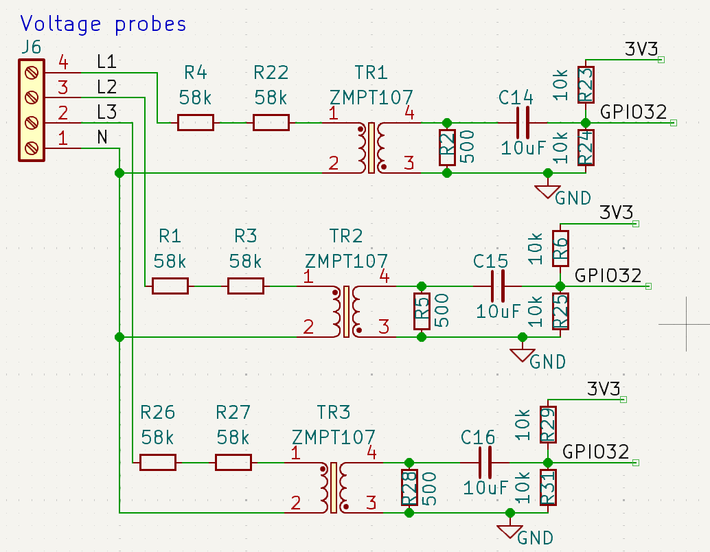
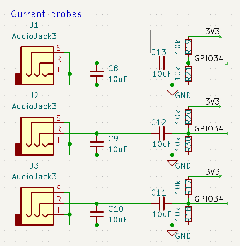
Hi everyone,
Im trying to make a powermeter based on ESP32 using EmonLib.
I have read a few finished projects on this but the one that helped me the most was from Daniel since I want to measure 3 phases.
Im located in Czechia, that means 230Vrms for each phase (Brown, Black, Gray) with neutral wire (Blue) and separated ground PE (Yellow+Green)
For measuring voltage I chose ZMPT107-1 transformer with burden resistor.
Current measurements will be done through SCT-013-030 (30A/1V~).
Once I get the prototype calibrated and working I want to make a custom board in KiCad to fit in inside a standard DIN rail box, but thats a story for another day (more like another year, lol).
Right now I have my own schematic, Im waiting for the parts to arrive and I would like to just double-check a few things.
I calculated the burden resistor for ZMPT-107 as I have seen here:
U_1 = 230V, U_2 = 1V
R’ = U_1/(2mA) = 230/0.002 = 115 000 Ohm → 2x58kOhm resistors
R = (U_2/U_1) * R’ = (1/230)*115 000 = 500 Ohm
I took the currents and voltages as RMS values so I hope I got that right.
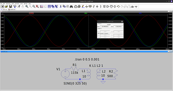
I even ran a quick simulation in LTspiceXVII and it looks okay.
Of course I added a 1.65V offset just as mentioned in the Docs.
To improve low current measurements I will be taking apart the SCT connector to properly connect the shielding and also add 0.1uF capacitor to filter out noise. Again the 1.65V offset was added.
I will be also adding a HDO detection, Im not sure how to translate HDO but it signalises the change between high and low tariff and its a separate 230V signal. I was thinking of using a capacitive divider with PC817 optocoupler but I have yet to decide that.
After reading a few posts here Im a bit skeptical about the ADCs in ESP32, does anyone have a recommendation on some 8 channel external I2C ADC?
Thanks in advance for all responses and advices I cant wait to dig deeper into this.
Welcome @Kalivjak - inputs seem sound. Re. the sampling and microcontroller:
Correct, the ESP32 series in general have poor peripherals, including the ADC. The main positive is of course the built in wireless connectivity.
I2C is borderline too slow for 8 channels at a reasonable sampling rate and resolution. You’ll want to look for an ADC that uses SPI instead as you can clock that into the MHz, rather than kHz.
Nicely leads on to a suggestion for an 8 channel, 10 bit ADC: Microchip MCP3008. This samples all 8 channels in parallel, so you would have to alter emonLibCM accordingly.
You can have a look, too, at the emonPi3 we’ve been working on for some more ideas. Hope that helps, and have fun
What is the 10 µF capacitor across the c.t.? This surely is a drawing error, according to what you write.
Also, I would use more than two resistors for R4 + R22 etc. The peak voltage across the two is approximately 360 V when you allow +10% for your supply voltage tolerance, having more than two reduces the voltage that’s across each resistor (of course) but it also lowers the current should one resistor fail to a short circuit. Have you checked the voltage rating of the resistors you will use? (And if the resistor specification does not say “rms” against the voltage, it means d.c, i.e. the peak a.c. voltage.)
I agree with Angus about the ESP32. Many people here have tried to use it, most use a separate ADC and ignore the one in the ESP32.
I have ordered MCP3008 to play around with it before I implement it into my design but it looks much better than the built-in ADC.
I havent looked much into the emonLibCM yet but I definitely will change that.
Thank you for all the suggestions!
Yes the 10 uF capacitors are meant to be 0.1 uF for filtering out the noise.
I was thinking about splitting the resistors into four as I have ready a few threads where you mentioned this but I havent updated the scheme yet.
Thank you for pointing out the wrong capacitor value.