In over my head?

Hi everyone. I’m new to econCMS, OpenEnergyMonitor hardware and this forum. I’m here to get get some help with the initial setup and then hopefully help with maintaining the documentation.

I want to focus on the problems I’m having first, because I either need to get them worked out, or return the hardware within the next 11 days.

What I’m trying to do

I want to monitor energy usage on all the circuits in my house. I currently have 25 breakers in my main panel and a couple sub-panels, and given the cost and complexity, I decided that I’m just going to try to monitor 18 circuits instead.

My motivation here is to see if we have some phantom loads because we’re using a lot of power and we can’t account for it with kill-a-watt meters and the built-in energy metering with our HVAC. We can always move CTs around after collecting some data, so 18 CTs should be fine.

Background about me

First, I’m in the USA. I have the typical American 120/240V @ 60Hz. I do not have any 3-phase power.

  • Programmed arduinos, including non-toy projects that used LoRa radios and are deployed in the field
  • Learned PHP in either the 90s or early 00s and have kept up with all their object oriented changes
  • Python is my jam
  • Javascript isn’t my favorite, but I have plenty of experience there
  • Linux is pretty much the only operating system I have used for years
  • Worked with lots of Raspberry Pi boards, including using the GPIO and I2C
  • Had a few years of schooling in analog electronics in the 90s, so I’m familiar with the basics
  • Have an open source thermostat, so I’m pretty familiar with US HVAC systems at this point
  • Kinda an open source fanatic, which is why this system was my first choice

For now, I just want to monitor my power usage. I don’t want to spend hours diving into the code, setting up additional in-house servers, writing documentation, or experimenting to try to figure out what works. I may want to do that in the future, but for now I’m just trying to determine if I can make this hardware and software work for me.

What hardware I have

  • emonPi2
    • Raspberry Pi 4b
    • emonVS UK 1-phase (yes, I ordered the wrong plug)
  • emonTx5
    • emonVS 3 phase North American split phase, no plug (yes, I ordered the wrong power supply because I saw North American and thought it was talking about the plug, not reading closely enough to see it was 3-phase)
  • Many CT sensors ranging from 20-100A

My main misunderstanding was that I thought I was going to be able to power the Tx5 over USB. I believed that since Raspberry Pi boards use 5V DC, and USB can provide the same, it’d just pass through. It was only after I got the hardware that I realized that it’s AC that’s going into the devices. As such, I intentionally ordered one without a plug, thinking that meant without a power supply. Oops.

I don’t know how I managed to order one with a UK plug. That wasn’t a misunderstanding but just a mistake on my part.

In the end, I don’t think any of this was a big deal, other than paying for extra component to be populated in the 3-phase power supply. I have plenty of power cables lying around, so I just opened up the emonVS units and wired in my plugs. Hopefully having the 3-phase thing doesn’t come back to bite me and if so, maybe I can remove a couple components and make it appear like a single phase power supply, if that’s necessary.

Hardware configuration

The emonPi2 and emonTx5 both have a emonVS is plugged into them, they’re connected via a USB-C cable, and I’m using ethernet for accessing the system over the LAN.

The current problem

The EmonTx5 is reading all zeros for all Pn and En values.

The emonPi2 seems to be working as expected and when I turned on the stove, I saw the P1 value shoot up to around 2500. So everything there seems to be good over there.

On the inputs page, all inputs for the emonPi2 and emonTx4 (the hardware is a 5, but it shows up as a 4 in the software) are green with the exception of V2 and V3 for the EmonPi2 (which are NULL). The Tx5 is reading a value for Vrms1 and tiny values for Vrms2 and Vrms3 (like 1.5-2V which I expect is just noise). In contrast, the emonPi2 has NULL values for V2 and V3. I’m guessing it’s because the components are missing from the power supply, but it might be some software setting that I don’t know about.

I thought maybe the device was detecting that I’m using a 3-phase power supply and might have switched into some other mode, so I tried switching power supplies. After doing so, the EmonPi2 still had NULL values and the Tx5 still had small values for Vrms2 and 3.

I’m not even sure what my questions are at this point, other than:

  1. How do I get power measurements from the Tx5?
  2. Are the power supplies causing these problems?

Why I think I might be in over my head

I thought I was going to clip on some ammeters, plug the pi into ethernet and power and be done. I’d be able to see all the power usage, have graphs, daily/weekly/month usage views and so forth.

After realizing that wasn’t the case, I see posts like Newbie from US and thing “yes, that’d perfect! They’ll probably have the same basic questions and I can spare people from answering them again”. Then I read the first paragraph of that post and realized that it was way more advanced than my “measure amps” use case.

I also never saw any explanation as to what P1-6 and E1-6 are in the documentation. Eventually I found a post that asked a similar question and the answer never said that “energy” is in kWh and “power” is in W, but it expected everyone to just know that somehow. In America, we use power usage and energy usage interchangeably. I thought maybe this is some terminology that electricians use, and I remembered seeing http://www.electropedia.org/ in the FAQ, so I looked up energy (hxxps://www.electropedia.org/iev/iev.nsf/display?openform&ievref=113-03-45) there and it says “Specific energy, or energy per mass, is denoted e or w.” To me that says that energy is measured in W, not Wh.

So even when I see these commonly used words and I kinda get the feeling that they might be used in a special way here, and I look them up in the source suggested, I still feel like I’m still struggling to get on the same page as the other people here on this forum. I was able to confirm my understanding in this case from the back and forth in the thread and running some tests on my local system, but if everything I try to do with this is going to take hours and hours of reading, I’m not sure this is the right system for me.

What I’m interested in doing later, maybe

If I keep this hardware, I want to update the documentation to help out people getting started who want a very simple system. I’m in a good position to do this because the problems I’m running into are not the same as the problems experts putting together a custom system are going to experience. I’m the one with the perspective of not just knowing that P1 is power in W and E1 is Energy in Wh without ever being told this. I know where I looked to find answers and didn’t find them. So as long as I can figure out the answers, I can put a link to them where I did look. In summary, I seem like an ideal person for the task at hand.

I also have PV, two ground source heat pumps, and am in the process of getting a whole-house battery backup system. So I feel like there’s a lot of really cool things that I could be monitoring.

When I looked at the Heat pump monitoring bundle, it asked about plumbing fittings and the diagram looked like it was going to require cutting open the coolant lines to measure flow rates. That’s way more invasive than I’m willing to take on. My PV inverters are SolarEdge, and batteries are LG, all of which have RS485 on them, so I feel like there are some opportunities there. The heat pumps are WaterFurnace and they have RS485 on them, use ModBus, and I saw someone has already reversed most of the protocol.

All of this is interesting, but not something I want to take on now, and certainly not within the 11 days that I have to either return the product or commit to it.
Welcome, Doc, to the OEM forum.

In over your head? Of course you are. Everyone here has been like that for a while when they’ve joined the community, but rest assured that there are plenty of people here who are ready and willing to help you. All we ask of you is you stick at it and don’t give up. From what I’ve read about you, you already have pretty much all the knowledge you need to be able to get along with your OEM kit just fine, all you’ve got to do is get a little way up that learning curve and everything will start to get clearer, especially when you’ve come across and had explained the bits that we do differently to the way you expect or are used to.

First, I’m an electrical engineer by profession, and I’m in the UK, so not totally familiar with US practice. My colleague @Bill.Thomson in Oklahoma, will no doubt step in and put me right when necessary.

Well, yes you can, but you also need the a.c. supply to be able to measure it. First lesson: if in doubt, ask here on the forum. Nobody here (unlike another place I can think of) will deride or despise you for asking the “silly” question, and it’s probably not silly at all, especially if it saves you dollars. Or as a colleague here says, “the silly question is the one that wasn’t asked.”

No it shouldn’t. Eventually, you’ll use L1 and L2 to measure your two 120 V lines. You won’t have a use for L3, so there won’t be a need to populate that part of your emonVs.

If you ordered a single-phase emonVS, then that’s exactly your problem. Do you want to measure the second leg voltage (i.e to have accurate power and energy readings for loads connected there, as well as 240 V loads) or are you prepared to accept a small inaccuracy by assuming the voltage on both legs is the same? Or maybe you/we can persuade ‘The Shop’ to supply a set of parts (a transformer, a fuse, a surge suppressor and maybe something else I’ve forgotten) to provide the second voltage sample.

Are you feeding it the same voltage sample (0.333 V rms nominal - it’ll actually be about 150 mV for you) measured by your emonVs? Because without a voltage to multiply with the current, you won’t read any power or energy (and yes, those really are different quantities. I’ll get to that later). I think you need this Shop | OpenEnergyMonitor - Shopping Cart and a RJ45 lead to share the 5 V and the line voltage samples between the emonPi and the emonTx. (You might get those over the counter locally.)

It sounds like that’s “one that got away”.

Yes, that’s right - and wrong. Energy is the time integral of power - the power multiplied by the time that power has been consumed (or generated), and it’s measured in Joules (1 J = 1 watt.second) or more usefully in watt-hours (Wh or kWh). Conversely, power in watts (or kW) is the rate at which energy is moved around. You pay for energy. If you were a large consumer like a big industrial plant, you might be surcharged if the maximum power you demand exceeds some specific value, because the supplier will need to ramp up additional generators to accomodate you. A lot of people (particularly broadcasters and journalists) don’t know the difference between power and energy and get it wrong.

Yes - and it’ll take a while, just like starting a new job at a new firm.

And we want that sort of comment - you probably won’t believe just how valuable that is, because as you appreciate, it’s so easy for those who’ve almost grown up with the system to forget that beginners start out, knowing nothing.

I won’t say anything about heat pumps, I know nothing in that area, so I’ll leave it to others who are far more capable than I am. But yes, inputs into your emonPi and emonCMS via RS485 and Modbus have been done before, easy if you know from the manufacturer which registers hold which values, hard if you’re the one to have to reverse engineer to get that information.

I appreciate all the answers and I’m happy to report that I’ve verified the Tx5 is capable of measuring power (and energy :wink:). :beers:

At this point there’s 16 more circuits to hook up, but I’m no longer feeling anxious about having to get the hardware tested as fast as possible to make sure it works before the return window expires.

The problem was either a testing error or the clamp on ammeters being bad or incorrectly installed (maybe got bumped when I was putting the face back on the breaker box?). I’m going to kill power to the house and investigate tomorrow night. I’ll post back so people aren’t left wondering what happened.

It was hooked up in an acceptable manner the entire time. I had one power supply (emonVS) per device (Tx5 & Pi2) and a USB cable in between. I like the idea of just having one power supply and using an RJ45 splitter. That will leave me with an extra 1-phase emonVS lying around, but that’s fine. It’d probably cost more in shipping to return it than it’s worth, plus shipping something across the Atlantic has a higher environmental cost than I’m willing to pay.

Tying up loose ends

I’m fine with having a little inaccuracy. I expected it to just assume 120V instead of measuring the voltage, so it’s already exceeding my expectations. But since I have a 3-phase emonVS, I should be able to split the RJ45 output and measure both legs to get the extra accuracy. I’ll have to get a 240V outlet installed there next to the breaker before I can do this, but that can be done.

In the meantime, should I just multiply the power & energy by 2 in the feeds for all the 240V circuits to get the [more-or-less] correct power usage?

Additional questions

I’ll post most of my other questions in other threads to keep things organized, but one that is still on topic here is:

Can I take my 3-phase and 1-phase emonVS units and move some components to give me two 2-phase emonVS units? It seems like it should just be a matter of pulling some transformers, caps, and whatnot and then soldering them into the other unit, but I thought I’d check here first. If so, is there a guide for that, or some reference documentation I can look at to figure it out?

Docs I want

This list is mainly for me, both to remind me what I want documented, and to hold me to account for actually getting it done and upstreamed. If there are things in the list that are already documented, please do let me know so I can link to them from… well wherever it makes sense.

  • emonVS pinout
  • US power monitoring buying guide
    • Not sure where it should go
    • Will be very short and point to the emonPi2, explain the emonVS and the option to use a 240V supply to get more accurate measurements
    • A separate section will talk about expanding monitoring capability with a emonTx5, including the option to connect them with USB or use the radios as well as getting AC voltage to them.
    • The guide should mention that lots of other types of monitoring are possible
  • Add a link to the getting started guide that shows how to get started if you don’t have a pre-flashed SD card
  • Improve the instructions about configuration
    • Might just be a matter of linking to some documentation for emoncms
    • Will include that Pn is power (in Watts) and En is energy (in Wh) for circuit n
  • Add some troubleshooting tips
    • Not sure where these should go, but I saw @AberDino asking for this over here Request: Troubleshooting Tips
    • Swapping emonVS units, swapping CTs around, checking for V1 or Vrms1 values, etc.

:+1:

Not directly connected - I’ve been working on automating the c.t. phase error measurements, and I got wildly different values to what I’d measured the hard (manual) way when I first received the ‘new’ 333 mV output ones - like 2 – 3 times the phase error :roll_eyes: tapped and wiggled the c.t, while watching the waveform on my 'scope, and it moved. So the problem is an air gap between the two halves of the core. Using the 25 A version, I measured the phase error: with only 0.001" in one side of the core, the phase error jumped from 1.4° to 9.4° - and when I thought I’d got a problem, the jump was only to about 2.5°. I wasn’t measuring the amplitude error - it wouldn’t have been that much as a percentage. But the phase error is different: with a ‘normal’ load with a reasonably good power factor it wouldn’t matter much, but with a poor power factor, the difference would be much more significant.

So yes, if the faces of the two halves of the ferrite core are not scrupulously clean, then you will have an accuracy problem.

Yes, exactly that.

In theory, yes. In practice, you’ll probably need a professional desoldering workstation to do it without damaging the pcb. Some tracks are on the top side and all are plated through holes, so there’s a high risk of damage. I suggest asking if The Shop can supply a single set of ZMPT101B, fuse and suppressor, or you can try to source the parts locally (transformer: ZMPT101B; TVS diode: SMBJ7.0A, Slow blow fuse, 1A X 250V: MST 1A 250V). Those are from the BoM for an earlier version, I think those have not changed.

Have you found the ‘Docs’ section here? I got those part numbers from that, there are also circuit diagrams and a whole lot of supporting information. Just make sure you don’t even think about trying to take it all in at once. :wink:

Not trying to nit-pick, but there is a big difference between the two…
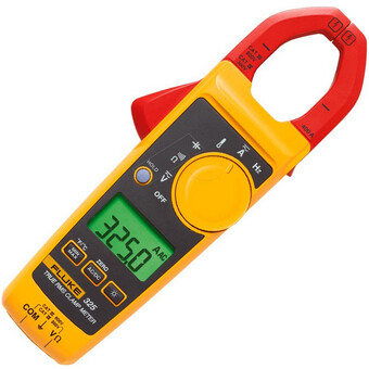
This is a clamp-on ammeter:

What you referred to as a clamp-on ammeter is actually a Current Transformer,
usually referred to as a CT.

You may actually be well aware of this, but lots of others make the same reference
without realizing there is a difference. :wink:
So this is aimed at them, as well.

You can do it that way, or you can simply install another 120 Volt outlet that’s connected
to the opposite leg the first outlet is connected to.

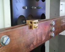
I’d read it as Doc actually meant a clamp ammeter - and he was comparing the c.t. readings against that test instrument when he knocked the c.t. and possibly re-seated the cores. As far as I’m concerned, a “clamp” refers to a busbar clamp - a genuine clamp which is used to make a temporary connection to a busbar without drilling it and bolting a lug on. One of these

http://www.goodproducts.com.au/products/products/bus-bar-cable-clamp-with-6mm-hole

It’s only comparatively recently that split-core current transformer has been called a “clamp”.
“Clamp” applied to a c.t. is totally wrong, I think it derives from a mis-translation from Chinese, or something equally stupid.

These are the lines that made me think he’s referring to the CTs as “ammeters.”

Absolutely no argument there!

I’ll use more precise terminology going forward.

I was calling anything that went around a wire and used the Hall effect to measure amperage a clamp-on ammeter. I’ll stick to referring to them as CTs from now on to avoid confusion.

1 Like

Saw this on another website where the question asked was What is Amperage?

At the bottom of the page, was the following post:

In the first circuits course of my electrical engineering program my instructor said

"If you are going to be a professional you must never use the terms amperage and wattage, the correct terms are current and power"

It seems the US electrical industry is stuck on the terms “Amperage” and “Amps.”
Weirder still, they use the term Ampacity to refer to the max current rating of wire.

I can’t remember any of the electricians I’ve ever spoken with, using the term current.

On the other hand, I can’t recall anyone in the electronics industry using the term “Amperage.”

But the c.t’s you use DON’T even use the Hall effect - they are pure transformers. OK, current transformers so they work “backwards” compared to the sort of transformer you’re more likely to be used to (like the one feeding your house - that’s a voltage transformer, and the one winding is a single turn (usually, but it doesn’t have to be), but they’re still transformers that rely on magnetic induction as discovered by Michael Faraday working for the Royal Institution in 1831.

@Bill.Thomson: I’ve occasionally heard “amperage” used by non-technical persons in the UK.

Pretty much the same over here, with the exception it’s quite a bit more than “occasional.”