Improve efficiency: Was it worth it?

@FredM67 This’ll “give you kittens” as we say in the UK.

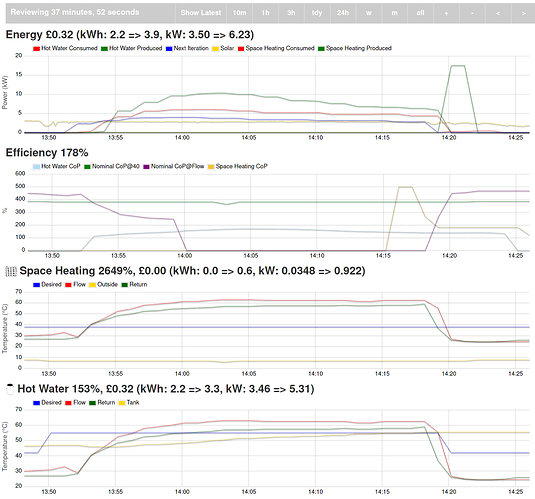
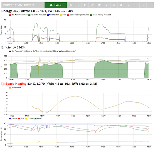
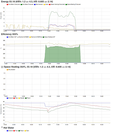
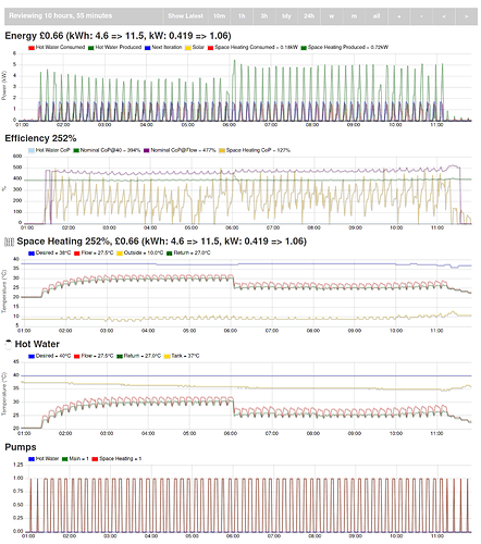
This is 2019-10-20 when the system was running with it’s default setup. As you can imagine, I didn’t want to leave the system behaving this way.

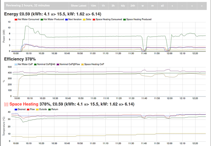
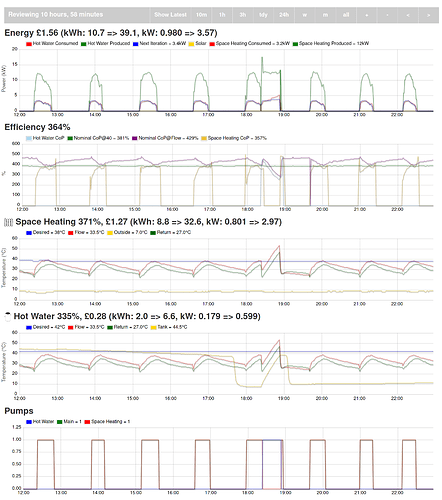
A similarly warm period of time now looks like this with the new control algorithm. Clearly there are more distinct cycles where it does work and then goes back to sleep. Hmm, it does appear to have cost twice as much. Off to ponder that.

Hi Trystan,

I also plan to wrap the house in a nice big blanket but I know I’m not going to get round to it soon so I was OK with being over-specced a bit. Our only backup is the log fire so erred on the side of caution, at the expense (literally) of doing badly when it’s warmer.

On the bright side, it was able to hoover up my solar PV today and quickly heat the tank to kill legionella before it got cloudy again :slight_smile:

Before I got Emoncms set up I wouldn’t have been able to easily see the solar versus heat pump curves because they were in two different systems. So, yet again, thank you for Emoncms!

1 Like

@TrystanLea My EPC rather pessimistically thinks I’ll be using 20,468kWh for heat and 2,975kWh for water heating.

That’s 140kWh/m2 a year for space heating.

At a rough guess, based on what we’ve used since October, it’ll actually be about 4,500kWh consumed and 14,000kWh generated for space heating which is 30kWh/m2 consumed.

Hot water should be about 2000kWh produced. Power consumption is a bit hard to gauge until I’ve been through a summer with the solar + heat pump + solar diverter. I’m expecting it to be about 1000kWh for a year. There are four of us.

Oil with our very old boiler was 2,000 litres a year so that’s 2000l * 10kWh * 70% = 14,000kWh so it’s about on-par with that.

Heat loss is pretty bad because we have uninsulated brick walls in two-thirds of the house. We have about 150m2 of wall and 100m2 of roof - there’s also a lot of quite big windows from the 1980s. I haven’t got a W/K figure yet.

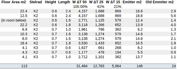
Here’s the relevant radiator info and room area in m2. The one wrinkle is that there’s a room with two radiators in it.

As you can see we now have about 6 times the radiator surface area that we had before.

As you guessed, we have a 14kW Ecodan so the power output can take the radiators to ΔT 25. If we imagine the rooms are at 21 °C then that puts the flow temp at 46 °C. With my compensation curve we’d have a flow that high when it is -5 °C outside.

compCurveValue = int(30 - effectiveOutdoorTemperature / 3)

Of course that’s all theoretical because it’s not 21 °C in the house. Some of the TRVs are at 15 °C and some are at 25 °C. It’s pretty hard to describe a house with occupants in random flux, especially in half-term week.

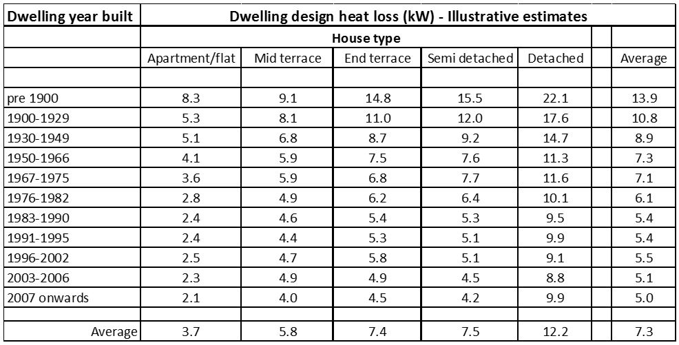
Clearly we need to stop the walls leaking heat so we can bring the power usage down. We’re in the pre 1900 bit of this…

However, if we look at a “cold” day (by UK standards) the we can see we’re consuming 1.26kW for space heating. When I think of something like my fan heater I used to use in my office which consumes 1.7kW I’m amazed that the heat pump is keeping the entire house warm whilst using less power.

I know the numbers still look bad to everyone here.

2 Likes

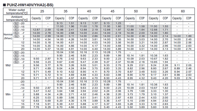
Thanks @MyForest Looking at the minimum output at 35C for the 14 kW ecodan it looks like ~6kW at 7C outside temperature. With ~1.5kW elec input.

If all your TRV’s were open it looks like you could absorb that heat at 35C flow temp and keep the heatpump running continuously? But maybe the house would get too warm?

Thanks for all the detail!

That page of their manual is my bible. It’s what I’m using to draw the “nominal” parts of the efficiency graph.

There’s no time like the present…

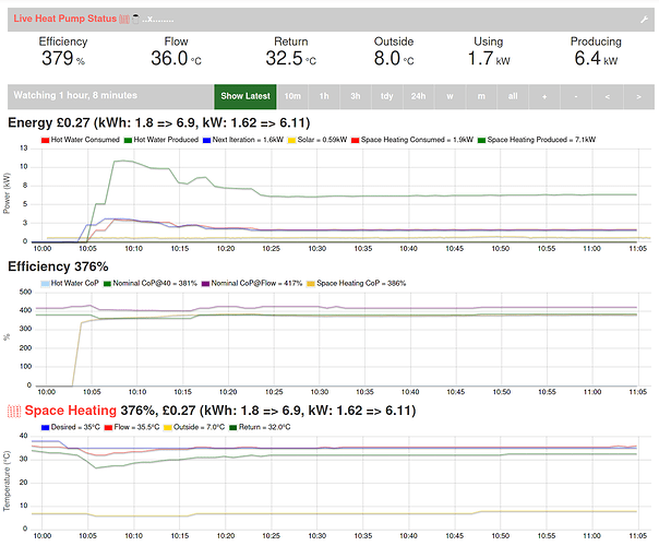
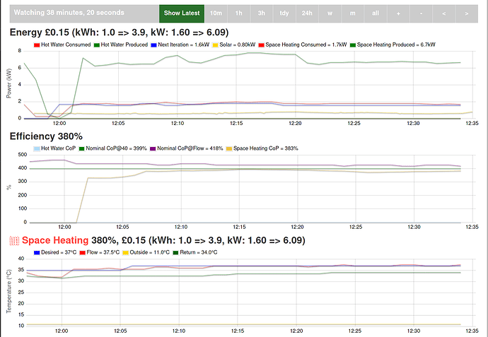
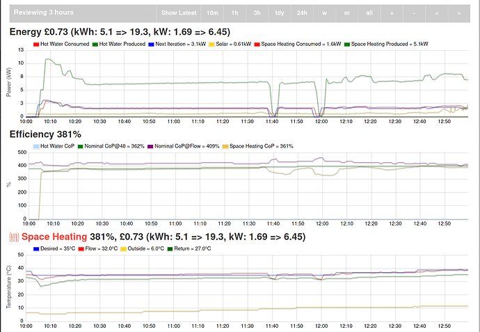
As you can see, it’s trundling along happily. It’s using 1.6kW though which is more than we’d typically be using. Here’s a recent comparison from a slightly colder day where the average is just under 1kW.

I’ve never seen it running stably like this for a long period of time, so now I’m seeing a thing happen that you all talk about that we should expect. The outdoor temperature went from 7 to 8 Celsius at 10:48. About 3 minutes later the return temperature also went up. That might be because the house is warming after an hour running the pump or it might be correlated with the external change. However the same thing just happened when outdoors went from 8 to 9…

So I think the changing external temperature is going to knock it out of steady-state because it’s getting above the target flow. I’m going to keep watching to see.

Of course if I raise the target flow to match the increased outside temp then the radiators will get even hotter and the house will get hotter and at some point it’s just going to be too much. Of course my efficiency will also fall - although it’s current 381% is pretty impressive. At the moment it’s modulated down to it’s minimum of 26Wh per minute (1.56kW) so we’re stuck with that well known problem of a device that’s rated for cold weather struggling to modulate down when it’s warmer. It’s a bit sad that the target cold temp is -2 and the current temp is 8 and it is struggling to manage comfortably across even that small range.

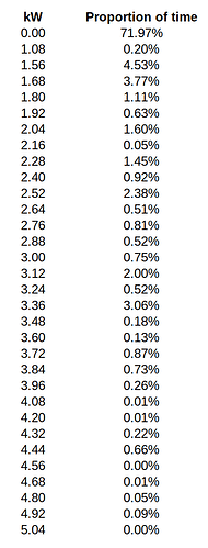
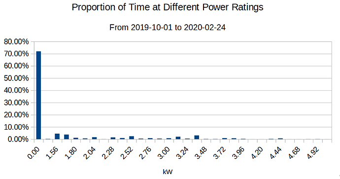
Here’s the buckets of power usage since 2019-10-01:

So it can go down to 1.08kW but it doesn’t seem to want to.

Clearly “off” is it’s most common state by a long way.

1 Like

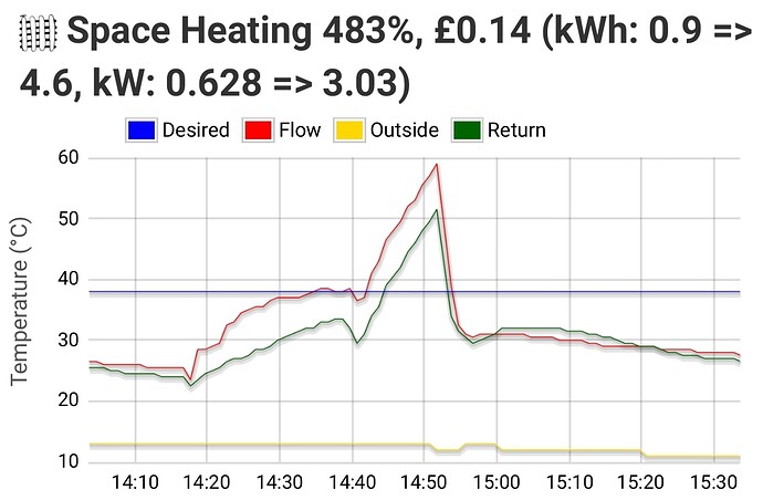
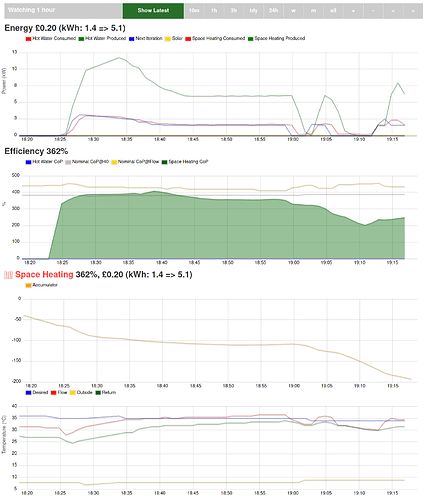
As expected we’ve started cycling.

I raised the flow temp to 37 and it’s modulated down so it’s using 1.6kW. The flow-return delta is 3 Celsius, that’s quite common here because the house is warm.

As we can see, the flow is still edging up above the target. I’m nudging the flow up to 39.

Unfortunately the sun is breaking through now and the outside temperature is rising. The heat pump just can’t cope running constantly when it’s this warm. Arguably it shouldn’t be needed, but of course our old house is leaking heat through the walls. So we need some heat, but not as much as we get from the pump running all the time.

Bumping it up does seem to have stopped it cycling, but the house is certainly getting too warm in a number of places now. I’m going to have to bring the experiment to an end.

2 Likes


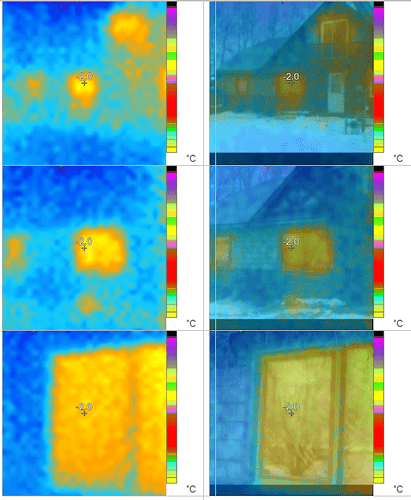
for your curiosity here my IR of my house it not as define as yours – the temp spread is from -5.0c the background temp and the hottest spot on the window at -2.0. on my worse window ( needs replacing) i but it is at the highest contrast. you notice my house irradiates as much heat as the the trees in the background from the the walls most of my heat loss it through the windows… interior wise I loose the most on the floor and infiltration/ventilation for tight house…

but also wanted to mention if you insulated from the inside- considering how you are heating your house as demand heating - those rooms would warm up faster.

2 Likes

Nice experiment @MyForest its got quite warm today hasnt it! Looks like your basically getting the COP and expected result from the datasheet, great stuff! Yes its a real shame they dont modulate down further… i guess that’s where buffer tanks and your forced longer period stop/start cycles come in…

1 Like

Wow @stephen that’s really good. You must be lovely and snug in there.

Your IR tool does a nice job of overlaying the photo into the thermal image.

Just for lolz…

Clearly it makes no sense to be heating when it’s this warm.

1 Like

The simple integrating controller in my non-modulating Thermia ground/underfloor heatpump works well. The greater the demand, the longer the compressor stays on.

In process control language it’s a cut-down PID controller (Wikipedia). Here’s a real-life example:

  1. Choose a target for the circulating water. Right now the outside temperature is 3 degrees C and the target is 26 degrees.

  2. Calculations

  • The integral is an accumulator which starts at 0 at switch-on.

  • Once a minute, measure the difference between the flow pipe to the underfloor and the set point. (Not the return because that varies less.) This difference is the “error” in process control.

  • If the flow temperature is X degrees below the set point, subtract X from the accumulator.

  • Or if the flow is X degrees above the set point, add X to the accumulator.

  1. Decisions, also once per minute
  • If the accumulator is -60 or below, turn on the compressor.
  • If the accumulator is between -60 and 0, leave the compressor in its current state (on or off).
  • If the accumulator is 0 or greater, turn off the compressor.
  • If the error is greater than 10 (i.e. too hot) turn off the compressor.

The thresholds at 0 and -60 provide hysterisis, and are adjustable.
The relationship between outside temperature and set point is also adjustable - typically a drop of 1 degree in outside temperature should increase the set point by 2 or 3.

Might be some ideas for you heat pump owners there.

2 Likes

Hi @Steve

Your algorithm is now running my house. Here’s how it’s performing.

The outdoor temperature is relatively stable at the moment, so for simplicity I’ll just show the actual set points in Celsius (outdoor temp → set point):

{“3”: 26, “4”: 28, “5”: 30, “6”: 32, “7”: 34, “8”: 36, “9”: 38}

I’m using the same constants in my implementation as you list above.

It got off to a rocky start because I was writing the code as it started running. It also caused a defrost which made the accumulator plummet.

You can see it’s starting to get more gentle now. The house is sensibly warm.

At about 17:15 the accumulator is rising, but the efficiency has dropped. The gold line is the nominal efficiency. At that point my control algorithm would have turned the heat pump off and let it all cool down.

I’ll add more updates if anything interesting happens.

As you can see from the energy graph at the top, this is a modulating heat pump and it had modulated down as far as it could.

1 Like

Bother, it’s gone out of control.

It’s 9 Celsius outside so the setpoint is 38.

However, the heat pump I have includes a “target flow temp” which I’ve constrained to 34 when it’s 9 Celsius outside.

So now the flow isn’t getting to the set point and the accumulator is diving down.

Lesson: The set point must always be less than the max flow temp.

I’ll intervene.

That’s fast coding, David! It helps that you knew your system well beforehand.

Suggest to experiment with different values for the -60 threshold, to tune it to the thermal inertia of your system. No doubt you already worked out that a smaller negative number means too much cycling, while a bigger number means more temperature overshoot/undershoot.

Thanks for the kind words @Steve. I’m sorta cheating because I’ve set myself up for experimentation with this Emoncms app and the way “actions” can contribute to my control algorithm.

My system isn’t blending well with the algorithm because it has a “target flow temp” and the accumulator algorithm is expecting the flow to just keep rising so would trigger the “diff>10” rule.

Within the gentle bouncing behaviour, I’m seeing it behave pretty reasonably. As you’ll see in the graph below, I obviously intervened around 19:30.

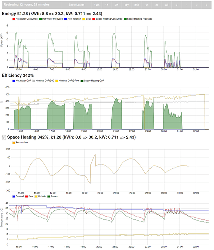
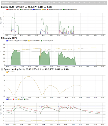
Here’s the whole experiment:

So there’s a few interesting things going on.

The defrost at 15:00 was handled pretty reasonably.

The shutdown at 23:07 was because the flow was set to a low temp. It’s a common problem when it’s warm (say 10 Celsius outside) because the flow required to dump all the heat would make everyone too warm. The accumulator had a gentle pause and then resumed. My control algorithm would have shut it down (for about the next hour or more). Notably the efficiency dropped off during that lull. However, the CoP of 3.81 during that time is pretty nice. As before, the gold line on the efficiency graph is what the vendor puts in their manual.

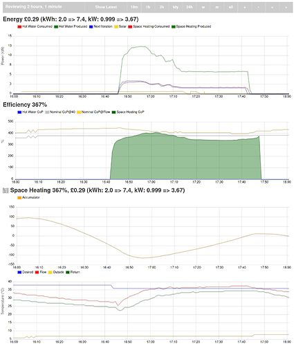
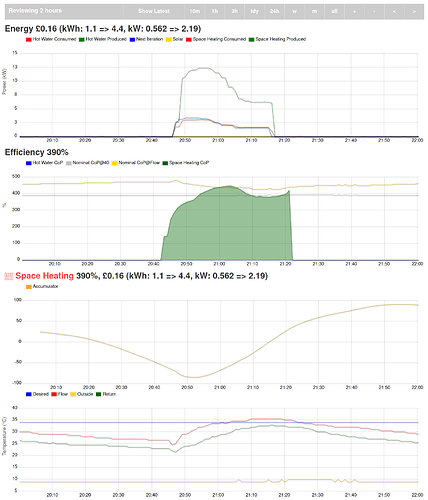
This couple of hours in the graph below is interesting because it seems to be behaving really nicely. I think that’s how we all imagine it behaving.

I had a similar couple of hours yesterday (in the graph below) and now I’m torn. We can see the accumulator was more efficient in CoP terms, but it used 2kWh rather than the 1.2kWh I used yesterday. I’m always striving for better efficiency, but I’m finding the long cycles that give good CoPs are actually consuming more energy so I’m experimenting with turning it off a bit more.

I left it unattended this evening which is a bit unfair. As you say, the thresholds need tweaking to make it run more smoothly. We can see how the “target” flow temp kept falling as the outdoor temp got warmer (yes, in the dark!)

I thought I’d share this next picture as an example of where tweaking is required because we can see around midnight it starts to cycle because the max flow temp is down at 33 Celsius. In that scenario the “set point” I coded was 31 so there’s not much change per cycle and we can see it ran for over an hour and was fairly unhappy. In that last run the CoP was 2.6.

Eventually it got to 11 Celsius outside and I hadn’t coded flow temps / set points that far so it stumbled and stopped doing anything. The heat loss from our house at that point is (finally) very low so arguably it could just shut itself off there. Unfortunately I know the others were all sat under blankets at that point to keep warm :slight_smile:

Here’s another example of it behaving really well. It would make a good pairing with a buffer thank like @FredM67 has:

Part of what I’m doing with the experiments is playing old data through new algorithms. I can pick any point since the heat pump was installed and ask a new algorithm to tell me what it would do at that point in time. Unfortunately, without being able to actually act back then, it can’t change the state to implement it’s behaviour to cause a long-run simulation. I haven’t figured out how to do that yet. Of course I could simulate the device which John and Trystan did, but that would be the theoretical behaviour, not what would happen in my real setup. So at the moment I’m not sure how to do robust evaluations of novel control algorithms. One way is to just let them run, but that only gives you a small data set on a limited set of scenarios as we saw with our accumulator run today.

The other thing that’s important to me (and not everyone of course) is that I’m looking for the system to be robust. When there’s a squally shower that drops the temp by 5 degrees I want it to handle that. When there’s a power cut I want it to jump back into action and do the right thing as soon as it can. This is hard to balance with squeezing the ultimate performance from the system. I can only imagine this is going to get worse when I try to integrate with solar, an agile tarif and a car / battery using the demand shaper.

Running the experiment has given me some interesting ideas to try out.

Firstly I think I should see if I can go for lower flow temperatures and potentially longer runs. That’s a similar outcome from when I experimented using Trystan’s algorithm.

Secondly, I’m pondering how the sporadic hot water demand will affect this. I’ve been “resetting” the flow by pushing the hot water round the radiators and I think that would work with the accumulator, you’d just need to pause it when heating hot water.

Is your system doing space heating and hot water @Steve?

I should also add a big “thank you” for sharing your algorithm so concisely. It made re-implementing it trivial.

It’s nice that Emoncms made it easy for me to add something like the accumulator value to the graphs. That would have been a chore in the vendor app / site - it would have inevitably ended up with spreadsheets and lots of copy-n-pasting which makes me sad.
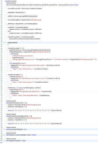
Just for posterity, there’s the implementation.

I tried to mimic your English description as much as possible so it would tally when people were comparing it.

I could go on endlessly about the things I normally do differently but that doesn’t matter. I should mention that this does run in a Docker container that fires up each minute so it uses a file to store the accumulator state.

Oh, the other thing that’s probably worth pointing out is that I turn off the pumps when we get to the “off” states so that might be different to how other people have it.

(posting as an image else it’ll be a huge wall of text in the thread - actually it turned out OK, see the next post)

import sys
import datetime
import logging
import os

from typing import Generator
from .action import Action

from .temperature_thresholds import TemperatureThresholds
from .target_water_temperature import TargetWaterTemperature

from .device_infos import DeviceInfo, DeviceInfos

# --------------------------------------------------------------------------------
class Accumulator:
    @staticmethod
    def accumulate(calculationMoment: datetime.datetime, deviceInfos: DeviceInfos) -> Generator[Action, None, None]:

        currentAccumulator = Accumulator.readAccumulator()

        deviceInfo = deviceInfos[-1]

        setPoint = Accumulator.getSetPoint(deviceInfo)

        currentHeatingFlow = deviceInfo["FlowTemperature"]

        difference = abs(setPoint - currentHeatingFlow)

        if setPoint > currentHeatingFlow:
            newAccumulator = currentAccumulator - difference
        else:
            newAccumulator = currentAccumulator + difference

        if newAccumulator != currentAccumulator:
            Accumulator.writeAccumulator(newAccumulator)

        logging.debug(
            "The flow is "
            + str(currentHeatingFlow)
            + " and the set point is "
            + str(setPoint)
            + ". The accumulator is was "
            + str(currentAccumulator)
            + " and is now "
            + str(newAccumulator)
        )

        if newAccumulator <= -60:
            targetTemperature = Accumulator.getTargetFlowTemp(deviceInfo)
            if targetTemperature != deviceInfo["TargetHCTemperatureZone1"]:
                yield Action(
                    "SetHeatFlowTemperatureZone1",
                    targetTemperature,
                    "Setting target flow temperature to " + str(targetTemperature) + " °C. The flow is currently " + str(deviceInfo["FlowTemperature"]) + " °C",
                )
            if not deviceInfo["Power"]:
                logging.info("Turning on because accumulator is now " + str(newAccumulator))
                yield Action(
                    "Power", "true", "Accumulator is " + str(newAccumulator),
                )

        if newAccumulator >= 0:
            if deviceInfo["Power"]:
                logging.info("Turning off because accumulator is now " + str(newAccumulator))
                yield Action(
                    "Power", "false", "Accumulator is " + str(newAccumulator),
                )

        if difference > 10 and currentHeatingFlow > setPoint:
            if deviceInfo["Power"]:
                logging.info("Turning off because difference is " + str(difference))
                yield Action(
                    "Power", "false", "Flow temp difference is " + str(difference),
                )

    @staticmethod
    def getSetPoint(deviceInfo) -> int:
        outdoors = float(deviceInfo["OutdoorTemperature"])
        outdoors = int(outdoors + 0.5)

        return {"3": 26, "4": 26, "5": 27, "6": 28, "7": 29, "8": 29, "9": 30, "10": 31,}[str(outdoors)]

    @staticmethod
    def getTargetFlowTemp(deviceInfo) -> int:
        outdoors = float(deviceInfo["OutdoorTemperature"])
        outdoors = int(outdoors + 0.5)

        return {"3": 40, "4": 39, "5": 38, "6": 37, "7": 36, "8": 35, "9": 34, "10": 33,}[str(outdoors)]

    @staticmethod
    def accumulatorFilePath() -> str:
        return "../accumulator.txt"

    @staticmethod
    def writeAccumulator(newValue: float) -> None:
        logging.debug("Setting accumulator to " + str(newValue))
        with open(Accumulator.accumulatorFilePath(), "a+t",) as accumulator:
            accumulator.write(datetime.datetime.utcnow().isoformat() + "\t" + str(newValue) + "\n")

    @staticmethod
    def readAccumulator() -> float:
        if os.path.exists(Accumulator.accumulatorFilePath()):
            with open(Accumulator.accumulatorFilePath(), "r+t") as accumulator:
                return float(accumulator.readlines()[-1].strip().split("\t")[-1])
        return 0
1 Like

Yes my Thermia system does hot water too, although not often – 2 or 3 times a day for about 10 minutes – since we have low usage.

During that time the algorithm loses sight of the flow temperature so the designers used a “carry on as before” strategy: each minute they re-use the last error reading from the minute before the start of the HW cycle. Usually this means the accumulator drifts more negative, giving the desired “catch up” effect after the HW is done.

1 Like

Thanks for showing the code. Is the mapping array in getSetPoint the right way round? Would expect the set point to fall as the outdoor temp rises.

You’re quite right.

I was too focussed on the set point relationship to the flow temp, but it’s actually a proxy for the heat demand figure for the house.

What you are looking for is for the set point to cause the accumulator to drop more often when it’s cold outside so you need a higher set point when it’s cold to give a larger difference and more action.

I’m now using this:

28 - (2 * outdoors / 3)

which hits the 26C at 3C outside point.

-10 34.7
-9 34.0
-8 33.3
-7 32.7
-6 32.0
-5 31.3
-4 30.7
-3 30.0
-2 29.3
-1 28.7
0 28.0
1 27.3
2 26.7
3 26.0
4 25.3
5 24.7
6 24.0
7 23.3
8 22.7
9 22.0
10 21.3
11 20.7
12 20.0
13 19.3
14 18.7
15 18.0
16 17.3
17 16.7
18 16.0
19 15.3

Unfortunately it’s racing away positive because the flow is 27 at the moment, it’s 8 outside => set point of 22.7 so the “difference” is +4. The system is off and the flow will fall to 22.7 in about 2 hours and then the accumulator will start to turn negative. However, it’ll then take 4-6 hours to pull it back down because it’ll be at something like +400.

I would expect the system to come back on within an hour or the residents are going to start shouting at me.

To do that I need it to go from 0 to -60 in an hour so I need the set point to be a smidge higher than the flow. If I make the set point at 8 C to be 28 that would do the job. So I’ll adjust the curve to be:

setPoint = 34 - (2 * outdoors / 3)

which gives these set points:

-10 40.7
-9 40.0
-8 39.3
-7 38.7
-6 38.0
-5 37.3
-4 36.7
-3 36.0
-2 35.3
-1 34.7
0 34.0
1 33.3
2 32.7
3 32.0
4 31.3
5 30.7
6 30.0
7 29.3
8 28.7
9 28.0
10 27.3
11 26.7
12 26.0
13 25.3
14 24.7
15 24.0
16 23.3
17 22.7
18 22.0
19 21.3

On my first cycle it now says:

The flow is 25.5 and the set point is 28.7. The accumulator was 0 and is now -2

So we’re in the right sort of behaviour.