How much noise is normal with multiple CTs plugged into the same ADC?

Fairly new to electronics and new to these forums. So sorry if I say or do something stupid or against the rules. Also, sorry for the long post.

I’m working on setting up a system to monitor my house’s power. I think I have everything working pretty well, but I’m getting larger amounts of noise than I expected.

  • I’m using 8 SCT-013-000 (input 100amp, output 50ma) which are a bit big for most of my circuits (two 100A mains, one 50A, one 40A, two 30A and a few 20A because I had extra CTs), but should work just fine.
  • I’m using an ADC to convert the signals to digital
  • Data is being read by a python script on a raspberry pi running emonpi (vanilla raspberry pi, not the emonpi enclosure)
  • All the CTs are sharing an op-amp to supply the stable 2.5v reference (as outlined https://openenergymonitor.org/forum-archive/node/673.html and https://learn.openenergymonitor.org/electricity-monitoring/voltage-sensing/acac-buffered-voltage-bias)

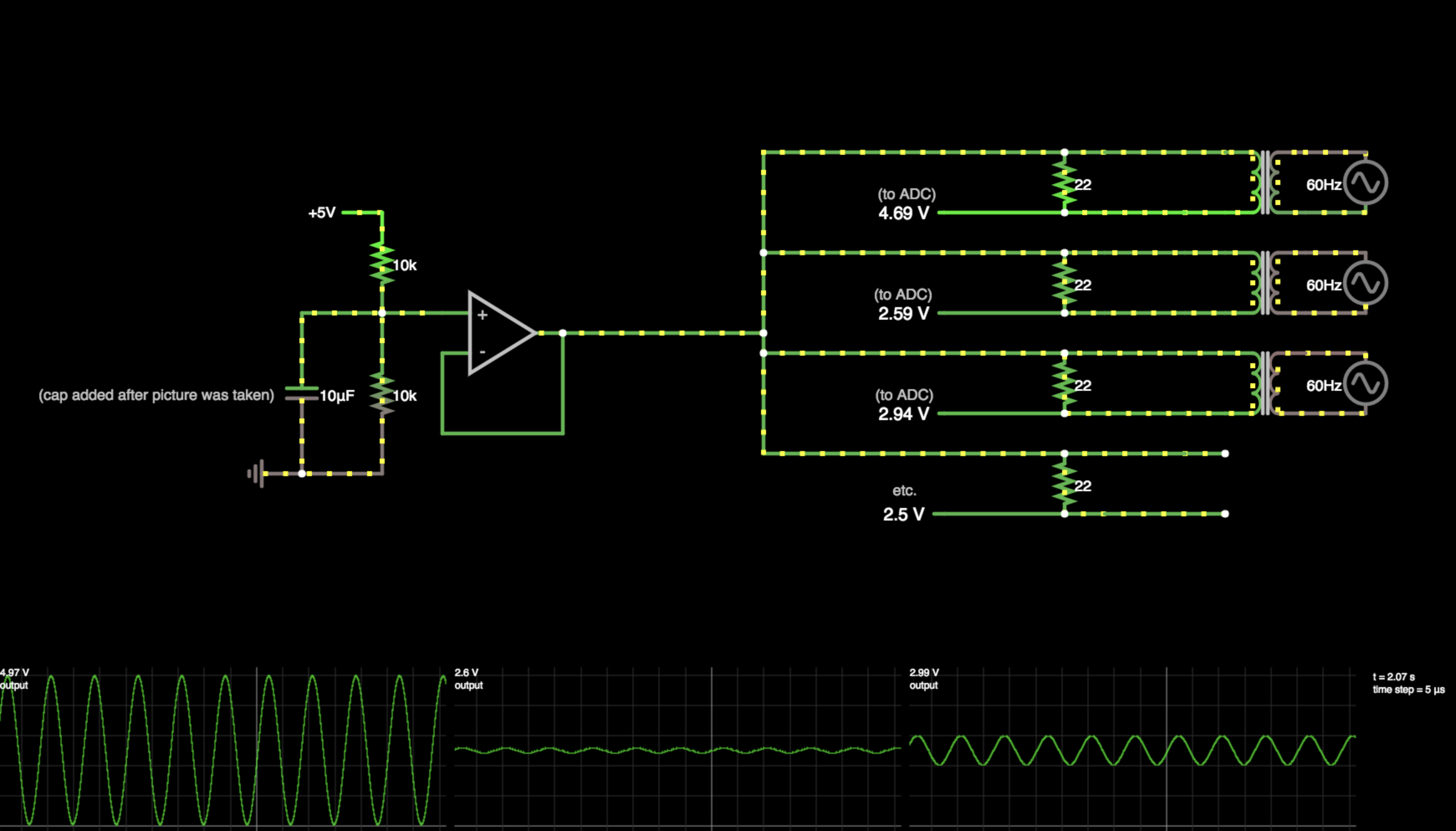
Here’s a rough diagram: (diagram shows a cap between the voltage divider and ground, which I added to try and reduce the noise, but upon further research, it would only fix HF noise on the input, which isn’t my problem)

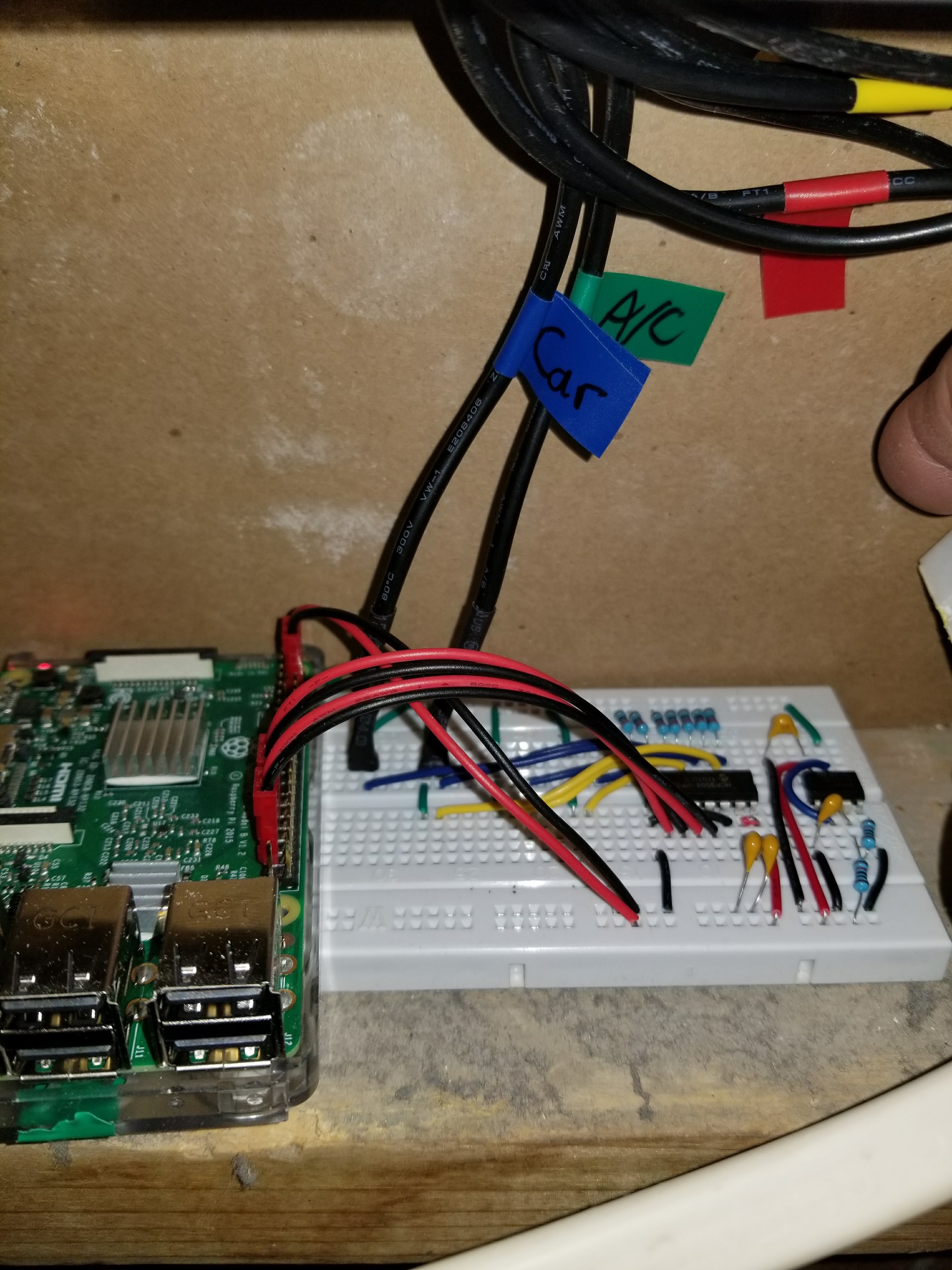
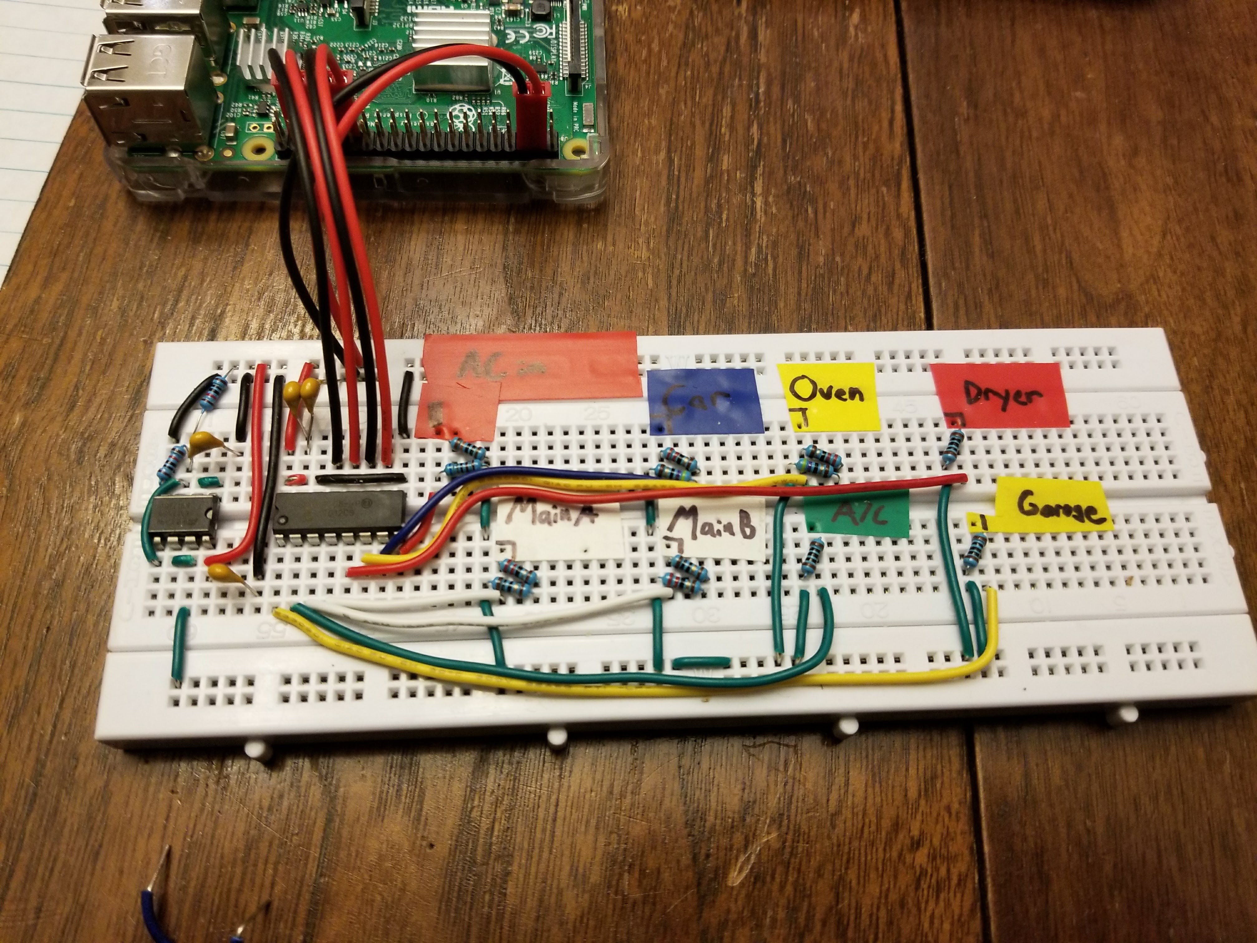
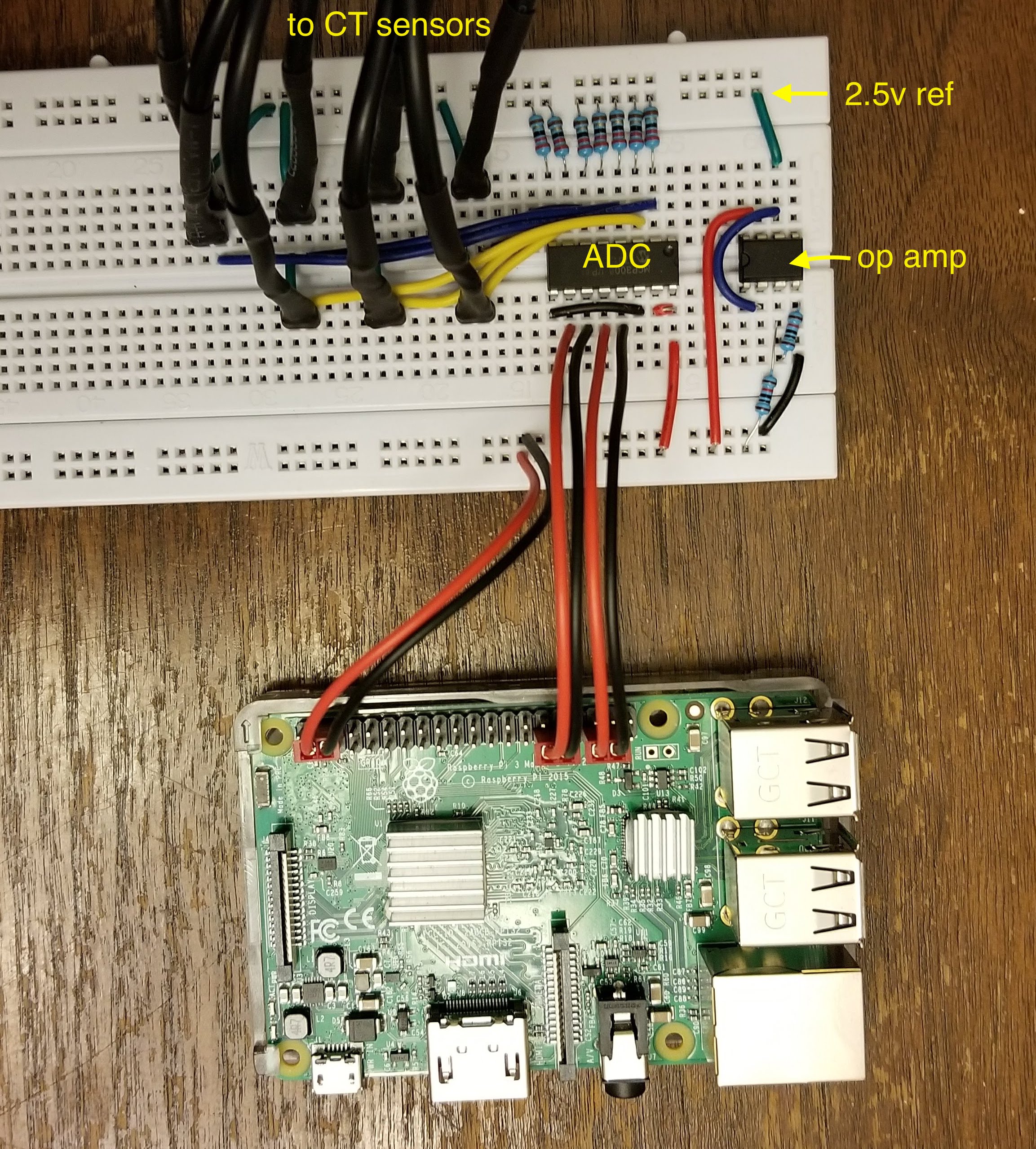
And here is a picture of my current breadboard. Sorry the wiring under the CT leads is a mess and hard to follow. Basically each CT lead is connected by green wires to the 2.5v ref, and then either a blue or yellow to one of the input pins on the ADC. There are also 22Ohm resisters between the 2.5v ref and each ADC input pin. I’m only using 7 pins, because I plan to add a AC/AC transformer for voltage measurement soon.

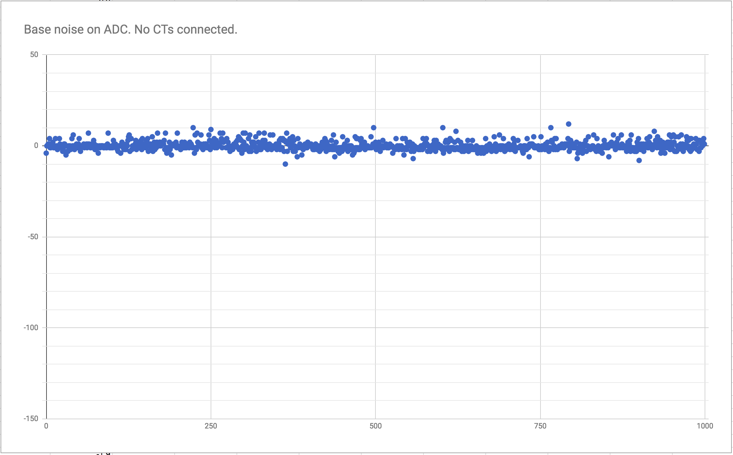
This all works fine when I only have one CT sensor plugged in, but once I have multiple, everything goes wonky. To show you what I mean here are the readings from the ADC with nothing attached to any pins. So no CTS even connected to the board. So it should be measuring the base noise of the PI, ADC and 5v source all working together. There is some noise as expected, but 93%+ of the values are within 1% of 0. (Sorry for the weird range on these graphs, it’s a 10 bit ADC so 1024 counts. For these measurements I subtract 512 so it’s centered on 0. And yes, I don’t have an oscilloscope, so I wrote a script to output csv and imported to google spreadsheets)

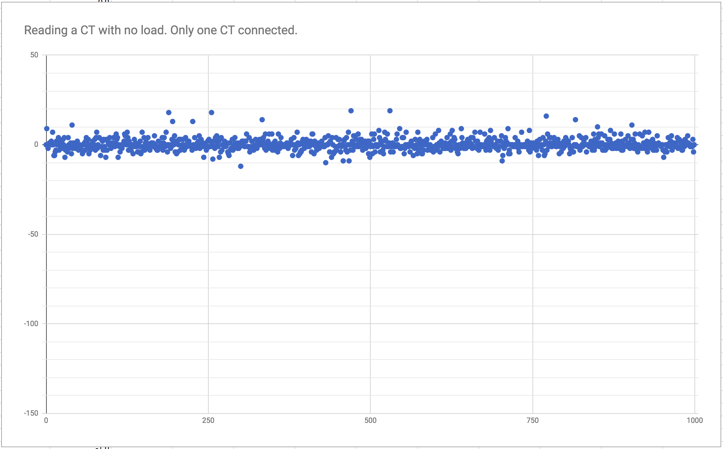
Here are the readings while a single CT is plugged in, but with no load on it. Slightly more noise, but I get values of around 100-200W, which is way better than I would expect given the tolerances of all of the components.

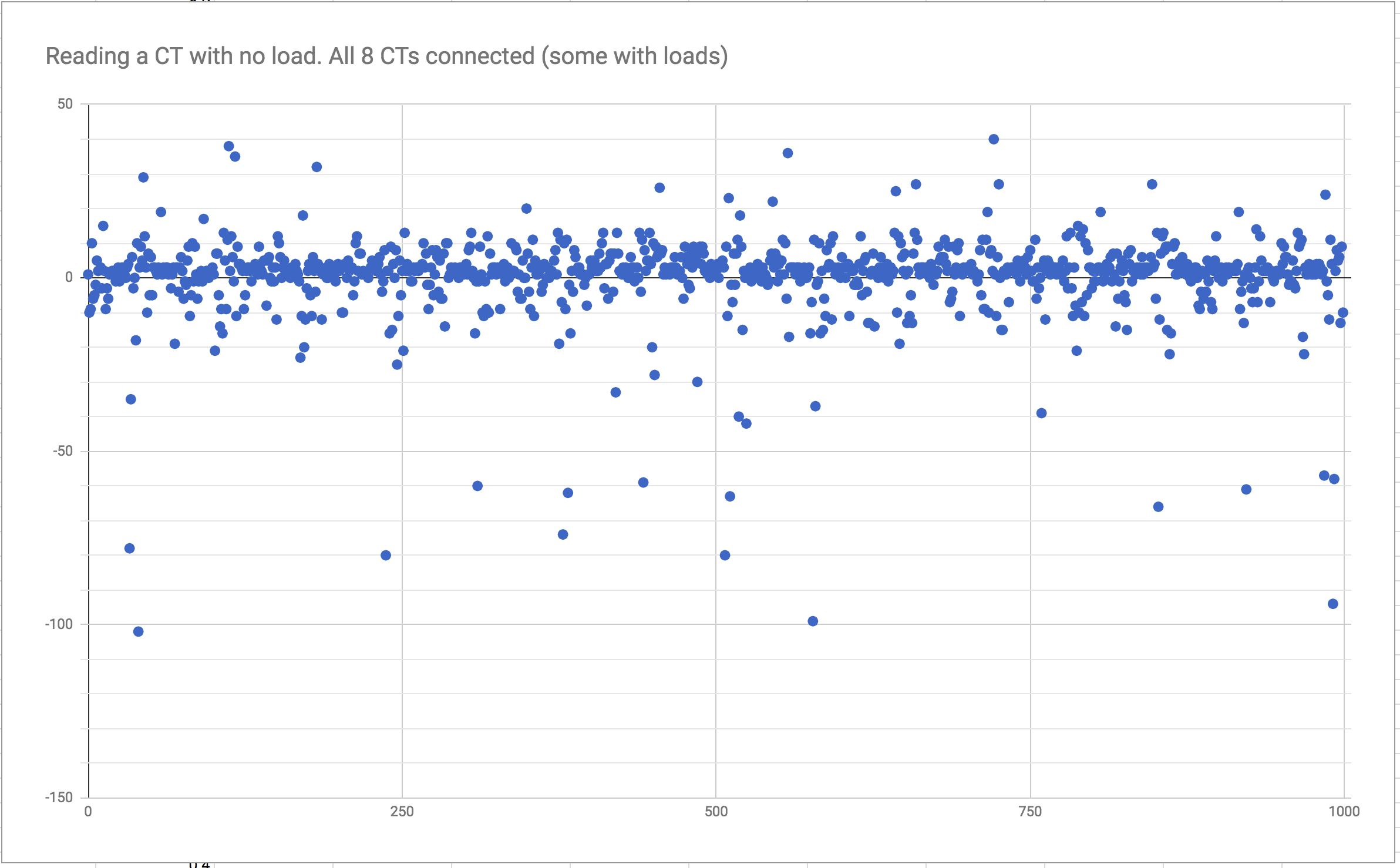
The problem comes when I plug all the CTs in, some of which are measuring loads. This is the readings from a CT without any load (not even a wire going through it) but while the other CTs are plugged in.

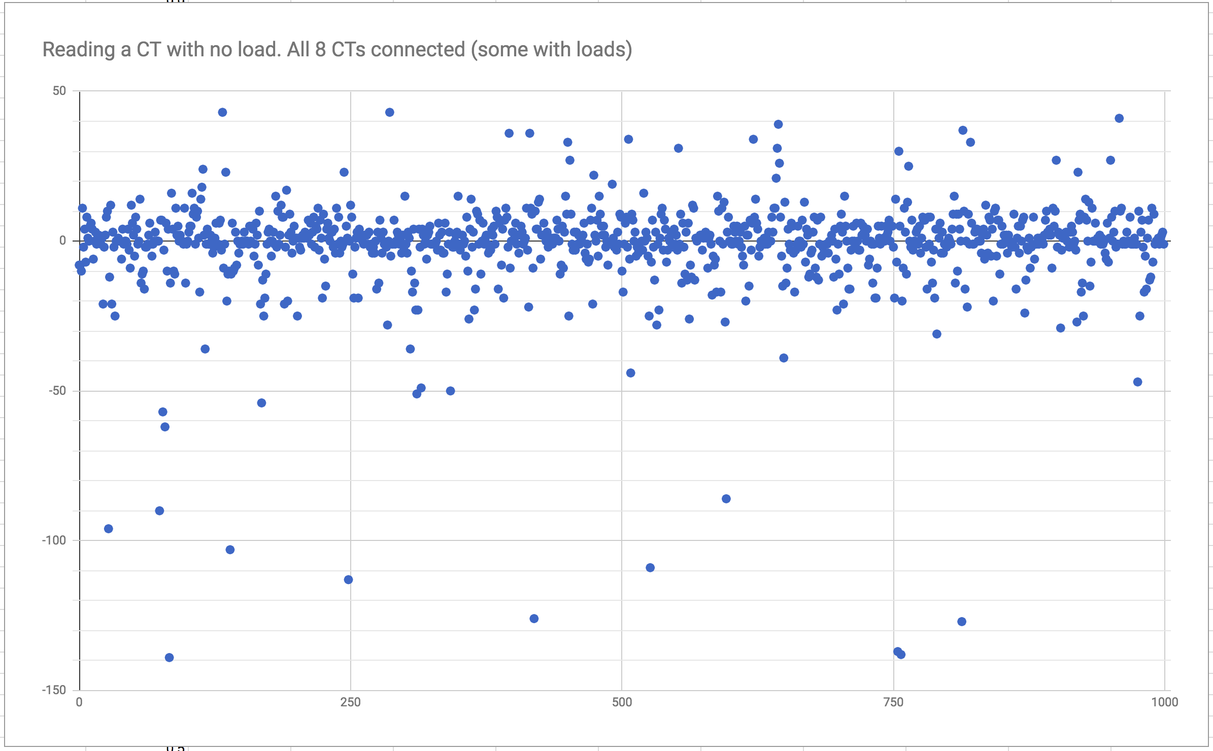
As you can see, the noise level has increased by a lot. My rudimentary RMS function calculated that this was using around 8% of the 100A max while unloaded, which makes calculating a rough estimate of power usage pretty useless when my calculations say every circuit is just always burning 8A when it’s really not.

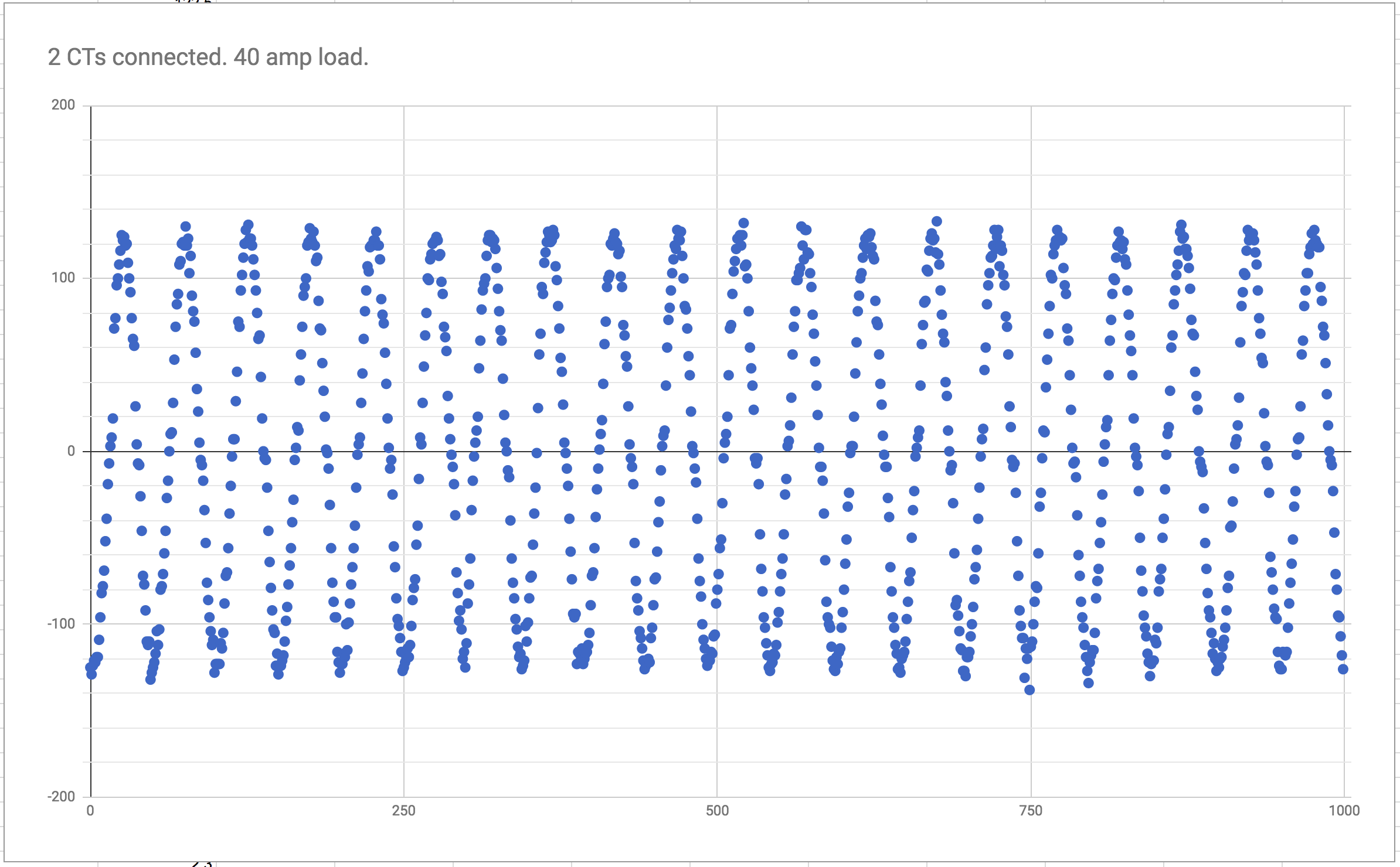
For reference, here is a 40A load measurement, again while all other CTs are connected.

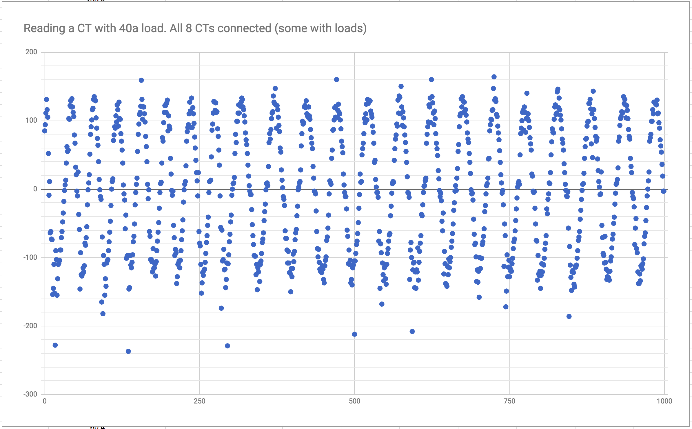
Still some random bits of noise, but the calculations come out pretty accurate to what I get with 3 different ammeters. The problem though is that in emoncms this circuit shows as pulling 40a when on, and 8a when it’s off (due to the noise) even though it should read close to 0. I’ve been working an implementing a fast fourier transform to filter the data I’m getting, but while I work on that my questions are:

Is this amount of noise normal and expected with multiple CTs sharing a 2.5v ref point from an op-amp? Have I done something incredibly stupid or missed something obvious? I know my CTs are oversized and I don’t expect miracles like being able to tell a single lightbulb being turned on, but measuring 8% usage on an unloaded circuit using rudimentary RMS calculation seems off.

Presumably you have set the ADC up to scan the input pins in sequence at high speed. If you just concentrate on a single channel, does the apparent noise fall?

Not so any more - I’ve elevated your permissions. So please edit your post and include the material. Thanks.

My script does 1000 samples on one input, then move on to the next (1000 reads on pin 1, 1000 reads on pin 2, etc.). This is done every 20 seconds and feeds it to emoncms. Though, for these tests, I actually just did 100 reads on a single pin, so none of the other pins were even being sampled when these graphs were made.

Thanks, I edited my post.

I don’t see any decoupling caps - breadbard layouts are likely to pick up noise anyway. I suggest at least say 0.1uF between Vcc and GND shortest path possible for both ADC chip and the op amp.

With 7 burden resistors present on the inputs to the ADC, but with only one c.t. (no primary current) connected across one burden resistor, you get “one ct noise.png”

What do you get when you have only two c.t’s connected, the one you’re looking at on no-load, and the (adjacent?) one at full load? What I’m getting at, is it noise or recognisable crosstalk from an adjacent circuit?

I too don’t see a decoupling capacitor across the supply to your ADC. See sections 6-4 & 6-5 on the data sheet. They recommend 1μF.

That’s been true here for a long while. I don’t have meaningful numbers, but the majority of complaints/questions about excessive noise concern breadboard layouts. A gut feeling is the noise is somewhere between two and five times what we see from an emonTx V3.4

But bear in mind that when you have your a.c. input, the noise ‘power’ that you see will reduce markedly, because it’s no longer being rectified by the rms calculation.

Could you try putting a 10uf capacitor to ground on the output of the op-amp?

Thanks for the suggestions Robert.Wall and emjay and overeasy! When I get home tonight I’ll try adding those capacitors as well as testing the noise increase with only 2 CTs connected, one with load and one without.

What’s the prevailing theory on why breadboards are more noisy? Is it because it essentially is a bunch of parallel wires attached to everything and that increases crosstalk?

Not only that, you can add in the ground connections may not be as good as they might be (so a few millivolts difference between points that you think should be the same), the supply when it reaches the sensitive parts might not be as solid as it might be (so as I suspect might be happening here, digital noise gets injected into the analogue voltage reference) - it’s a combination of many things.

Okay, I’ve added some bypass capacitors and it has made a what appears to be a small bit of improvement. Here is a new graph of readings from a CT with no load, but while all other CTs are plugged in. It’s pretty similar to the last one, but to my eyes the clustering seems slightly better. Though there is a repeating cluster (or a repeating of the cluster being broken up?), and overall the baseline is pushed up by a few counts but I have a high pass filter in my code that takes care of that.

This picture shows the cap I added, as well as the setup for the 2 CT load test which I’ll get to in a moment. 2 .47uF near the bottom totally 1uF for the ADC, one .1uF on the Vcc of the op-amp and another on the 2.5v ref voltage divider that feeds the op-amp. I tried adding it after the op-amp on the 2.5v line and it seemed to throw everything out of whack.

And here are the results from having 2 CTs plugged in, one with a 40A load (Car) and one with no load (A/C).

With only 2 CTs, the noise level on both is much, much lower, but I don’t see anything that stands out as interference between them, so I’m starting to think it’s mostly just base level noise from all the components and CTs, compounded by the breadboard, etc.

In other news, my AC/AC adapter came, so I’ll work on hooking that up, which should help quite a bit.

Another thing that might help, but I’m not sure if it would cause any harm: for the circuits that won’t get to the full 100A that the CT is rated for, could I use a bigger burden resistor? For example, the Car circuit is a 50A breaker, so I could in theory put a 70ohm resister and then change the calibration value so the numbers come out right again. This should reduce noise and get better resolution data. I believe the main concern would be saturating the core on the CT, but I couldn’t figure out how to determine what the limits are.

Thanks again for everyone’s input, I really appreciate it!

I presume that’s a single op-amp you have? (I can’t read the number on it.) If it is a dual one, put the second channel in unity gain follower configuration using the same 2.5 V bias is the first, but don’t use the output. Op-amps with floating inputs are a well-known source of problems.

Yes you can. Provided that you keep the voltage below 1.6 V rms at the maximum current that you want to measure, you should be OK. The c.t. performance and accuracy will suffer, so as with all engineering decisions, it’s a trade-off - here between c.t. errors and ADC resolution.

I was hoping to see a recognisable signal, but as there isn’t, it rules out a few possible factors.

Have you seen and read the various comments here about the quality of the power supply and which power input is best for Arduino boards?
Here’s one thread, there are many.
https://openenergymonitor.org/forum-archive/node/10111.html

It’s a single opamp. Part number UA741CN

Thanks for the link regarding the power supply. Right now I’m using a 5v usb wall wart that came with the RaspberryPI, so that is potentially a source of noise. I’ll do some research and see if I can find a higher quality power supply.

I also have a few spare op-amps so I might set up several of them to see if splitting the CTs among several op-amps helps instead of them all sharing a single one.

A 741 on a single supply of 5 V? I think you’re pushing that to, or past, its limits.
The Texas data sheet http://www.ti.com/lit/ds/symlink/lm741.pdf says “The μA741 device is specified for operation from ±5 to ±15 V;”

I’d advise getting one specified for single supply operation. I’m not convinced this is your main problem, but its certainly not optimal.

I hope using several op-amps won’t make a difference. The big advantage from using one is, assuming you have one ADC and a multiplexer in front of it, you only need to determine the d.c offset once, then you can subtract the same number from all 8 channels, so simplifying and speeding up the software.

Ah, you are right. How does something like http://www.ti.com/lit/ds/symlink/lm158-n.pdf look? It says it can handle “Single Supply: 3V to 32V” and it’s a dual op-amp so should avoid the floating input problem you mention earlier.

Also, what do you mean when you say you “assuming you have one ADC and a multiplexer in front of it”? I understand that a multiplexer would be a way to select which input to read, but I thought that’s what the ADC is doing as my code on the Raspberry pi instructs it which input pin to read.

How are you going to mount it? You probably want the LM358 variant.

You must avoid the floating inputs to the spare op-amp.

You have a multiplexer and an ADC that are packaged together inside the MCP3008. But they are separate functions. The multiplexer selects the input that the ADC converts. The inference (that you missed) is that as there is only one ADC, it will always see exactly the same d.c. offset for each input, which might not (probably would not) be true if you had more than one ADC due to non-linearity errors. So all I was saying is you can simplify and speed up your code significantly because you don’t need to detect the d.c. offset 8 times.

Yeah, the LM358 was what I was looking at, that pdf came up in a search for it, and includes it in the diagrams, sorry, I should have specified which I meant.

Oh, I misunderstood what you said earlier, and thought that dual opamp had an inherent advantage, but upon rereading I see that you clearly said that if I had a dual I need to make sure to not leave the inputs disconnected. Thanks for pointing out that I misunderstood that.

I understand that the 2.5v reference being created by the voltage divider and op-amp isn’t guaranteed to be exactly half of the 5v ref being fed into the ADC, therefore you need to deal with this d.c. offset somehow. My code (originally based on Raspberry pi ,mcp3008, and python script substitue to emontx ? | Archived Forum but I’m adding voltage sensing and realpower calculations from EmonLib/EmonLib.cpp at master · openenergymonitor/EmonLib · GitHub) solves this currently using a digital high pass filter. You are saying that it would be more efficient to calculate the dc offset once, then apply it to all the readings, since the offsets will all be the same. If I were to add another ADC, I would need to calculate the offset for each ADC, since they would likely be different. Is that correct?

Once again, thank you. You have been very invaluably informative and helpful!

That’s correct.

Actually, there’s a better way to calculate the offset than using a filter - at least, it’s theoretically sound and appears to give better results. It’s based on the formula for the rms value of a complex wave. The way I’ve implemented it is to remove the nominal offset (only to reduce the size of the numbers) then accumulate separately V2 / I2 / instantaneous power and the raw samples (voltage will be your favourite - to give the average, i.e. the d.c. value). So the only maths you do per sample are a subtraction, a multiplication and an addition, all of which are integers, hence fast. Then at the end of the sampling period you subtract the offset using the formula.
You can also extract PHASECAL from inside the loop because it’s a constant, and apply that once to the whole sample period. That way, there’s no slow floating point maths done on every sample. There’s but one snag - it assumes the d.c. bias doesn’t change over the sampling period.

emonLib Maths (extended).pdf (154.3 KB)
(Where it references calculations to be done in emonHub, you do that outside the loop before you send the resulting values on to wherever they’re going. EmonHub doesn’t accept this input format, it’s a proposal at this stage.)

Hello, here’s an update. I made the following changes:

  • Added the ac adapter for voltage readings
  • Updated code to calculate realpower using instantaneous readings
  • Changed the burden resistors on some of the smaller circuits
  • Replaced the op-amp UA741 with LM358

The AC adapter and accompanying calculations made a HUGE difference, just like Robert said it would. Rather than the RMS calculation compounding the noise, it basically gets cancelled out now, because roughly half of the readings add to the calculation and half subtract. The other changes seem to have helped as well, but not as drastically.

Below are readings from a circuit with no load. Still some noise, but the calculation comes out well because the noise cancels out due to being multiplied by the voltage.

And here is a reading with a load:

Pre ac-adapter (and other fixes) emon graph:
Readings in emoncms before adding the AC adapter. You can see the base noise for a 120v circuit was nearly 800w. So large things would show up just fine, but anything small was lost in the noise.

Post ac-adapter emon graph:
Unloaded circuits now read +/- about 50 watts, which is about as good as I could expect from the components I’m using, so I’m happy.

And here is the new breadboard layout:

Thanks again to everyone’s help, especially Robert. :smiley:

1 Like