I’ve been looking for a means to monitor my house energy usage for a while. I discovered this site thanks to Google.
The electricity supply into my house uses three wires, with 230V between all three. One of the three wires is used as neutral, and the other two are used as live. I think that this means that the electricity coming into the house uses a Delta topology, as distinct to a Wye-topology
Does your monitor measure energy usage for this scenario?
Yes, we can do that. There’s a sketch for the emonTx (only the emonTx, not the emonPi) for “approximate” measurement of a 3-phase supply, and it can be set up as in your case to treat one phase as the neutral, so that the second phase is shifted 60° in relation to the first.
By “approximate”, I mean the emonTx has only one voltage input, therefore it is accurate so long as the voltages of the two phases you are using are the same (or the same within a error band that you find acceptable).
To do the measurement, you’d need an emonTx, a.c. adapter and two c.t’s, then if you want to log and record the data using emonCMS, you need in addition an emonBase and power supply. You can buy emonCMS on an SD card, or you can download it free of charge.
If you think (or know) the two voltages you use vary too much from each other, then you can treat your supply as two single-phase supplies. In that case, I’d suggest an emonPi to measure one phase and run emonCMS, and an emonTx to measure the second phase and send the data to the emonPi. If you do that, you need 2 × a.c. adapter, 2 × c.t, 1 × Raspberry Pi 5 V d.c. power supply, 1 × emonTx, 1 × emonPi, emonCMS.
Which of those two schemes you choose might depend of exactly what you want to measure in total, and what you foresee you might want to measure in the future. The emonTx has four current inputs, the emonPi has two. If you want to measure more than the total house consumption, then all the other things you want to add will affect your decision.
The emonPi has two CT inputs, can I use that, or do I have to use the emonTX? You mention both in your reply. Is it that the emonPi takes the measurement with two CTs connected as two single-phase sources, whereas the emonTx is a true 3-phase measurement system?
In the meantime I’ve browsed further through the site, and came across this post from Belgium. I also live in Belgium, but in my case, only L1 and L2 are used as live circuits and L3 is used as N. In that post, there is a reference to a special 3-phase version of the firmware. Is that the version I would have to use?
I checked the voltage cross the two phases using a cheap voltmeter, and they are identical, but this is probably not an accurate indication.
Sorry the late reply here. I was distracted by other ongoing issues.
You mean: If I want the shop to install the sketch for the emonTx, I have specify the values of the parameters in that doc file to the shop. Is this to allow them to compile a special sketch for my situation? Or is it enough to specify that I have three cables coming into my house, 230V tension between them all, one of which is used as N, and the other two used as L?
WIRES: 3-WIRE is an available option, however, only 2 of the three are load-carryng in my case
NUMSAMPLES: In my case, I assume I will only need 2 CTs, but this isn’t an available option
Some of the other options I don’t understand
Yes, you will only need 2 c.t’s. Unfortunately, the sketch becomes far too complicated if you don’t define 3 c.t’s, but there’s no need to have and fit the third.
If, having read the PDF, you still don’t understand, then you need to ask. It may well be that you don’t need those options, or they don’t apply to your installation.
**Initial Configuration**

#define USEPULSECOUNT 1 => set to 0
#define PULSEINT 1 => leave unchanged for emonTX v34
int nodeID = 11;  => leave unchanged

**EEPROM Memory**

EMONTX_V34 => leave unchanged
SERIALPRINT => comment out
USEPULSECOUNT => comment out
PULSEINT => set to 1 (same as PULSEINT above)
EmonTx V2 = 0 => leave unchanged
EmonTx V3 = 1 => leave unchanged
PULSEPIN => set to 3
PULSEMINPERIOD => leave unchanged
RFM69CW => set to RFM69CW (leave unchanged)?
RFPWR 0x99 => What value to use if I buy antenna from the shop?
nodeID 11 => leave unchanged?
networkGroup 210 => leave unchanged?
VCAL 268.97 => leave unchanged?
I1CAL 90.91 => leave unchanged?
I2CAL 90.91 => leave unchanged?
I3CAL 90.91 => leave unchanged?
I4CAL 16.67 => leave unchanged?
WIRES 3-WIRE => even though I will only use 2 CTs
CT1Phase PHASE1 => phase that feeds the a.c. adapter
CT2Phase PHASE2 => how to determine: phases 2 & 3 follow phase 1 in that order?
CT3Phase PHASE2 => even though it is unused?
CT4Phase => unused
I1LEAD 2.0 => leave unchanged
I2LEAD 2.0 => leave unchanged
I3LEAD 2.0 => even though it is unused?
I4LEAD 0.2 => even though it is unused?

**PLL & ADC Constants and Settings**

LEDISLOCK => comment out
SUPPLY_VOLTS 3.3 => use default
Default: 3.3
SUPPLY_FREQUENCY 50
NUMSAMPLES 36
ADC_BITS 10
ADC_RATE 64
LOOPTIME 5000
PLLTIMERRANGE 100
PLLLOCKRANGE 40
PLLUNLOCKRANGE 80
PLLLOCKCOUNT 100

**Calibration**

Not applicable, since I want to use standard components
To place the order, I would have to send these value to the shop by email?
Would it be possible to define standard configuration for typical scenarios:
Standard setup, all components bought from shop
EU / EU
Single / 2-phase / 3 phase
No, as soon as you define it, it’s USED. So comment it:
“1. #define USEPULSECOUNT
As it stands, pulse counting is enabled. To disable it, make this line a comment.”
If pulse counting isn’t wanted, all the settings for it become irrelevant.
What are these? I don’t recognise them.
0x99 is the standard that works for most people. You only need to turn the r.f. power up if you have a range problem, and then you’ll need a 5 V USB power supply to give you the extra power that the transmitter will need.
Those are the standard values. Leave them unless you need them changed.
Yes, you have a 3-wire (no neutral) system.
Yes, but which is it going to be? Only you know that. You must find out which phase the socket that feeds your adapter is on.
Again, you must determine that. Hopefully, the phases are labelled correctly, but beware, sometimes it is wrong.
If you have a choice of which wires to put the c.t’s on, then you best option will be:
CT1 → PHASE1
CT2 → PHASE2
CT3 → PHASE1
CT4 → comment out
You can have 45 if you wish, as you’re on a 50 Hz system with 3 c.t’s.
Yes. Whether they can do this at present, because everyone is working from home, I don’t know.
No. There are far too many permutations for that to be realistic. The default values should work for what is most likely to be a “standard” 3-phase installation. As I understand it, your 3-wire system is no longer being used for new installations, and those are getting a 230 / 400 V 4-wire system instead.
I know there must be a reason why you want the shop to do this, but you would have much more freedom to set the system up as you need, if you had a programmer and installed the Arduino IDE on a computer. You would then be able to set all these things yourself, but more importantly, change something if it turns out that what you asked for is wrong.
What are these? I don’t recognise them.
=> My mistake. These are allowable values for this
PULSEINT
Defines the interrupt number for pulse counting:
EmonTx V2 = 0,
EmonTx V3 = 1,
EmonTx Shield – selectable, see the Wiki
Yes, but which is it going to be? Only you know that. You must find out which phase the socket that feeds your adapter is on.
=> I have three cables coming into the house. No identification. One is used as N, so if I use one of the remaining two as Phase 1, then the other must be Phase 2. Does this make sense?
No, because the timing difference between them is vitally important. With your system, Phase 1 is the reference (I define it that way) and Phase 2 follows it 60° later. You must have the a.c. adapter on Phase 1, or you will only get the correct value for your power under very limited conditions.
If you cannot do that, I will need to add yet another setting option to the sketch - which you don’t like.
So I would need an oscilloscope to measure the phase difference between the 2 L cables?
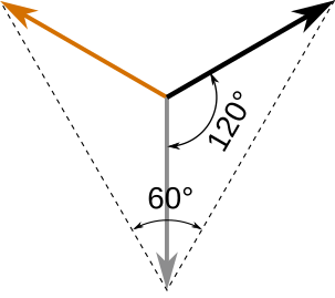
BTW: you mention 60° phase shift. Why 60°? 120° surely, since 360 / 3 = 120°?
Believe me, it’s 60°. The angles at the star point, where the voltages are 132 V, are 120°. from the tip of the phase you’re calling neutral, the angle is 60°.
Look half way down this page Learn→Electricity Monitoring→AC Power Theory→3-Phase Power→3-Phase Power at the rotating phasors. The star point, where you don’t have a connection (but it’s probably earth) is the centre of the diagram about which the phasors are rotating.
If you think of the tip of the blue phasor being your neutral, then the tips of the red and yellow phasors - the phase voltages - are 60° apart with respect to your neutral.
[Edit]
You can check that your mains supply is what I believe it to be by checking all the voltages.
If it is a 3-phase supply with no neutral, you will measure 230 V between any two phases.
If one phase is called “neutral” and is earthed, you will still measure 230 V between each phase and neutral, and between the two phases. You will also measure 230 V between each phase and earth, but only a very small voltage (less than about 10 V, and probably a lot less that that) between neutral and earth.
If the star point is earthed (this is unlikely - I would call it dangerous), then you will still measure 230 V between each phase and neutral, and between the two phases. You will also measure 132 V between each phase and earth, and between neutral and earth.
[/Edit]
What you really need to do is establish which phase your a.c. adapter will be on. You should be able to look inside your distribution board - or trip a circuit breaker/pull a fuse out - to identify it, and the board should be marked to show which circuit is fed by which phase.
I don’t understand the 60° explanation, but I believe you.
I checked my mains supply again, and it is exactly as you described. The tension between any two phases is 230V, and between any phase and earth is 115V.
I have an old mains energy meter, which I believe was designed for Wye wiring, and it doesn’t work with my Delta wiring. For some - not all - circuits, the meter indicates double the actual wattage. It is an earlier version of this meter. For example, when I switch on the dish washer, it indicates that about 5.2 kW are being consumed. This is why I want to replace it with something more accurate. I think that when the house was wired, one of the phases was used as N, with the other two phases L1 and L2. However, I think that some circuits are connected across L1 and L2, instead of across L1 or L2 and N, and this might explain why the meter indicates double the actual power consumed. Does this make sense?
If those voltages are correct (and your 115 V really is 115 V and not 132 V) then you have a North American type “split-phase” supply. I didn’t think that has ever been used in Europe.
What I think you have is 220 V / 127 V system.
You write “The tension between any two phases is 230V,” Does that also include Phase - Neutral?
Can you carefully check all the voltages again, please?
What I need is the accurate value for each of these voltages:
L1 - N
L2 - N
L1 - L2
L1 - E
L2 - E
N - E
I don’t know your “this meter.” but looking at the instructions, it appears to be suitable for the UK single-phase domestic supply only and it can only give a “best guess” of power and energy as it can’t measure voltage nor power factor, so I’m not surprised it doesn’t give good data with your supply arrangements.
What I thought your supply was is this:
so if you can only connect your a.c. adapter L1 - N (assuming the grey phase is called “neutral”), then L2 - N is shifted 60° relative to L1 - N.
The length of each ‘phase’ arrow is either 127 V or 132 V, and given the angles between them, that makes the voltage between the arrow heads (the voltage you have at a socket) either 220 V or 230 V.
Regarding the 60° phase shift, brilliant explanation. Many thanks.
I’ve checked my voltages again, and you’re right.
I have three phases coming into the house, with exactly 234V across any two. The voltage across any phase and earth is 135V. My mistake.
I have no neutral cable coming into the house, which is why I thought I had a Delta wiring schema.
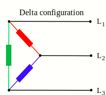
I thought that one of the three phases coming into the hosue is used as N. Something like the following diagram, where L3 is used as N, and L1 and L2 are used as L.
In this diagram, I was thinking that circuits connected across L1 and L2 (thus not using the L3 which I thought was being used as neutral) would explain the double measurement I wrote about in my previous message.
That’s a relief. The numbers you gave me didn’t make sense.
Yes, your loads are all wired between two phases, so it is indeed a delta configuration.
If you had a neutral, you could use the standard 3-phase sketch with 3 c.t’s. You could still do that if you could get a 132 V a.c. adapter and wired it between L1 and earth. But you’ll never be able to buy one of those. So the best answer is to use the 3-phase sketch in 3-wire mode, use one phase (say L3) as the “neutral” and measure the currents in L1 & L2.
As I wrote, I don’t know the unit you’re presently using. If it assumes 230 V and you put the c.t. on any one incoming line, then it will give the apparent power according to the current in that line. That might be the correct apparent power for that, but it won’t read the total for the whole house. Say you put the c.t. on L3, it will read for the green and blue loads, and miss the red load completely.
As the 3-phase article says, classical theory says you need one less wattmeter than the number of wires. Therefore, again treating L3 as the common or neutral, you can measure the current in L1 and the voltage L1-L3, and the current in L2 and the voltage L2-L3, and by multiplying to give the powers and adding, you get the total house power. On their own, the individual powers don’t have a physical meaning. I’m treating L3 as the neutral, even though strictly speaking it isn’t.
Now the awkward question of phase rotation. Are the incoming 3 phases labelled where they come into your switchboard?, and can you determine between which two the socket you’re going to use for the a.c. adapter is wired?
I need to know this because the emonTx has only one input for an a.c. adapter, so in the software it generates its own voltage for the second phase. If the a.c. adapter is connected L1-L3, then L1 is the first phase and internally it generates the L2-L3 voltage and you put the second c.t. on L2. L3 is treated as the neutral.
You can of course rotate everything - if the adapter is connected L3-L2, then the first c.t. goes on L3 and the second on L1 (L2 being the “neutral” this time).
If you have a free choice of the incoming cables on which you can put the c.t’s, then there isn’t a problem that you can’t rectify when you are installing the emonTx, and you can use it to identify the correct phases to put the c.t’s on. If you aren’t able to put a c.t. on one of the phases, then I need to know which that is in relation to the socket the a.c. adapter will be plugged in at.
Many thanks again for helping me with this, especially with helping me understand my house’s wiring.
The meter I’m currently using is capable of measuring 3-phase power consumption, I’m just don’t think that it can be used for Delta wired houses. I’m using 2 CTs conected to L1 and L2. For some circuits, it measures the double of the actual power consumption. For example, when I put the kettle on it measures 5.9kw, and if I remove either of the 2 CTs, the displayed comsumption is 2.45kW. I checked this circuit using a voltmeter, and it is connected across L1 and L2. That is, it is not using L3 as the neutral. Will openTx indicate the correct power consumption in this case?
Regarding your question about the labelling of the phases, no they aren’t labelled, There are 4 cables coming in, 3 blue amd 1 red. I blue is unused, the other 2 are connected to L1 and L2, and the red is connected to L3. But I will be able to determine across which two phases the AC adapter will be connected across.
I believe it will get close, but I can’t guarantee total accuracy. Because the emonTx uses the one voltage wave it measures as a proxy for the second - appropriately delayed by 60° - it depends on the amplitude of the second being the same as the first. This is normally never true, but it should be close, within a few percent but depending on the loads on the relevant cables both in your house and those of your neighbours who are fed by the same transformer.
[If you need better accuracy, then I think you need to look at a proper 3-phase meter that has a data output that you can send to emonCMS - and even if it’s permitted where you live, one of those is likely to need installation by an electrician as it will mean cutting your main incoming cables.]
I’ve never come across that combination before, nor can I find that in any of the sources I’ve looked at. I understood that some countries use red for the earth conductor, but that can’t be right in your case. It would be interesting to know what the unused blue wire is.
I think, if you have checked with the shop and they are willing to set up your 3-phase sketch as suggested, you are ready to go.
When you install the emonTx, you will need a resistive load, such as an electric heater, that you can connect to various phases. You need to know which phases it is connected to, so that you can move the c.t’s around to give the correct readings.
I’ve done the maths assuming the load is 1 kW, drawing 4.4 A approx. (the numbers will scale). This is what you should read:
Load Connected
I1
I2
P1
P2
L1 - L3
4.4 A
0
1 kW
0
L1 - L2
4.4 A
4.4 A
0.5 kW
0.5 kW
L2 - L3
0
4.4 A
0
1 kW
If you don’t get those values, then you will need to move the c.t’s around until you find the correct permutation. I cannot think of a way for you to find out the phase sequence safely without the proper test meter.
The unused blue cable has no tension, so I suppose that it is not connected at the utility’s meter. This means that it is a true Delta wiring schema, with no neutral.
I’m not concerned about the minor inaccuracies introduced by slight differences between the phase voltages. Your explanation seems to imply that across L1-L2, the indicated currents I1 and I2 will be “double measured”, but that the corresponding power consumptions P1 and P2 will be halved, so that the measured total power consumption should be the same when the same load is connected across L1-L2, L1-L3 and L2-L3. I assume that I still only need 2 CTs, not three? If only two, where do I connected them? On L1 and L2?
My next step is to contact the shop to ask if they can install the 3-phase sketch on the emonTx, using the parameters we discussed earlier. You mentioned that it would be easier for me to do this myself. I checked on the site and I found a reference to a USB to UART adapter to allow the sketch to be downloaded to the emonTx, but I couldn’t find the details. Do you know where I can find these?