Greetings from Belgium !
I am currently installing an OpenEnergyMonitor on my main fusebox.
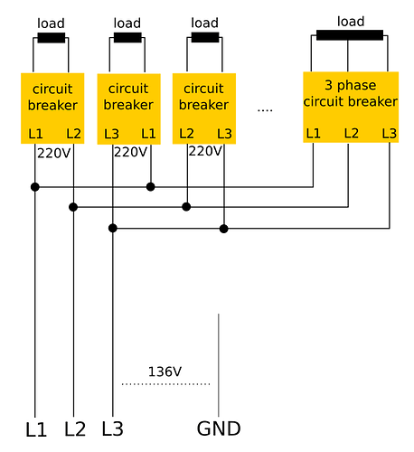
I live in Belgium, and my house is connected with 3phases - 3wires (no neutral, 220V between phases, 132V between phase & ground). Half of the country is wired like that, another half is wired with 1phase 220V, and industrial buildings with 3phases + N - 380v between phases
My “loads” are evenly spread between L1/L2, L1/L3 and L2/L3, but I also have 3-phases loads (motors for woodworking tools for example)
I am using the latest 3phases 4wires/3wires firmware, written by Robert.Wall (great work, thank you!) and followed the calibration procedure in the pdf
I have 3 ct and 1 voltage sensor pluged between L1/L2.
When putting all CT on the same wire with a resistive load (kettle of 2kW), I can adjust calibration values. Then, I set the sketch to 3-wire and each CT to the phase it will be used on in the sketch, leaving the c.t’s on the test load. I measure around 1.5x the load value and pf of 0.75. Great, like expected in the pdf.
But when I place the CTs on each phase at their final location (not all 3 on the load-test phase), I measure half the power (I have to change the orientation of all ct to get positive power)
I tested by moving the kettle around phases, and this is the output :
L1/L2
232.66 9.786 9.814 0.513 0.000 -1336.95 0.0 80.79 0.00 50.263 -0.2932 0.0 0.6774 0.0000 300.00 Pulses=0 PLL is locked
(power1+power2 = 1336W)
around 10A in ct1 & ct2 (what comes in, goes out)
L2/L3
234.31 0.283 10.262 10.141 0.000 -1345.16 0.0 2370.03 0.00 50.263 -0.5444 0.0 0.9974 0.0000 300.00 Pulses=0 PLL is locked
(Power3 give the correct result)
around 10A in ct2 & ct3
L3/L1
235.01 9.593 0.586 10.018 0.000 -1264.73 0.0 1136.12 0.00 50.292 -0.5287 0.0 0.4826 0.0000 300.00 Pulses=0 PLL is locked
power1+power2 = 1264W
power3 =1136W
around 10A in ct1 & ct3
any idea on what I need to modify in the sketch to make it compute the correct total power ?
Thank you


 …) so those thoughts are only driven by my logic and maybe I am missing the understanding of electric power consumption theory.