If you draw it (either with a drawing program or pencil & paper and scan it), then look for the Uparrow icon along the top edge of the box you type in. (Hover your mouse for words.) It should allow you to do that.
I’ll try to explain in terms of the diagrams here.
Try this for a line of thinking: Look at diagrams 1 and 4 on that page. You’re thinking that to get from 1 to 4, the current wave moves a half cycle sideways - 180° phase shift. It doesn’t really. What it actually does is it flips over top to bottom - it inverts. It appears to be the same thing, but it isn’t. To justify that, I’ll invent a magic black box that I can connect to the mains. I turn the knob on the front to “consume” and I see voltage and current as Diagram 1. If I turn the knob slowly towards “Generate”, the current wave will get smaller and smaller as my box consumes less power, the current will collapse to zero and then build up again like Diagram 4.
Actually, I don’t need to invent a magic box - you have one. It’s your inverter. Except it doesn’t have a knob on the front.
Does it?
Do they? I think not, to both. As far as the input to “AC Subpanel” is concerned, the power from the battery or PV is injected upstream of it. It hasn’t a clue where the electricity came from. You could rip out the PV & batteries, run 3 wires from its incoming terminals to the right place in the “Main” panel, and it will never know the difference. It always consumes power, the power flow going into it never reverses.
The power flow reversal happens on the two wires between “AC IN” on the inverter and the breakers on the “Main” panel, and all places upstream.
The matter of 120 V or 240 V has absolutely nothing to do with the direction of power flow. It’s a practicality - I could say a source of confusion - because you can’t measure two voltages because there’s only one voltage input on your emonPi.
My reference to reversing was a poor choice of words…my reversing was in reference to changing/reversing from a positive to a negative value. As in from grid source versus from PV source. Both are going to the AC Sub-Panel for consumption not reversing direction of flow.
Should not the Sum be Greater than the Parts?
For the Ac Sub-Panel I see Negative Value when source is from grid and a Positive value for when PV is the source…and the current direction is always the same for both. Fig.1 and Fig.4 explained this perfectly.
My battery is for grid/utility power loss and is used much like a generator for backup. Matter of fact, I have a whole house generator and it is only called on to recharge the battery when battery depletion reaches a setpoint and will run just enough to top off the battery once more and then shut down until needed again.
I assume you mean power? Where are you measuring that? If it’s at what you think is the input to “AC Subpanel”, and everything is wired according to your diagram, then I think things are not what you think you they are.
But you will see negative power as I illustrated above - on the Grid connection and on the “Input” (Grid) side of the inverter.
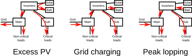
That probably explains the dual inverters. One will return power to the grid when there’s an excess of PV generation, but that will shut down when the grid supply disappears (it’s called “anti-islanding”), leaving the second one to supply the critical loads.
With negative value power added to a positive value power (Those parts) the Sum can not be a greater value.
Power1, Power2, Power1+Power2…if P1 is a negative value and then added to P2 that is a positive value the Sum of the two would be less than the two parts, had those two parts been both positive to begin with.
So, am I misunderstanding that the 180 degree out of phase generated power will have an opposite value to that of grid source power and while both had no reversal of flow direction?
And likewise do I misunderstand Fig.1 and Fig.4 referenced earlier in regards to 180 degree out of phase between grid and PV generatied power?
If so, then you are saying they are both the same value…not that one is read a positive and the other is read a negative?
I can see the power values reversed where the power flow direction reverses, no problem there.I do expect to see this there.
My trouble comes when the flow direction of power is always the same way and one value reverses to negative and causes the math to go way off. This happens when grid power is passed through bypassing the inverter when PV production is lost.
My two inverters are each 120 Volt…because in NA it takes two @ 120V to get my 240 Volt split-phase output.
If I understand correctly (and that’s a big IF ) I think this issue may stem from the OEM convention of reporting generation as a positive rather than a negative consumption. I stopped using that convention some time back as it was causing me confusion in places.
If the “power” is 180° out of phase it is flowing in the opposite direction. This is why flipping a CT orientation will give you the exact opposite polarity, (same current, PF and power, just the sign changes) The phase (0° or 180° unity load) IS the direction of “flow”, the sign of that measured value is relative to the CT orientation (and the VAC waveform which is your reference).
OEM convention says consumption/use/import is a positive and excess generation that gets exported back to the grid is a negative, and yet total generation is considered positive, as is solar that is self-consumed. So it depends where the solar is measured as to whether it is positive or negative ( ie it’s all pos when it exits the inverter, but any of that same energy that is exported is then neg at the meter/incomer/main CT)
I use the convention that generation is negative consumption, this fits well with the fact that inverters can consume power in times of low sun. The maths on this type of setup is much easier (and IMO more accurate eg inverters do not “generate” a small amount over night in the dark). This way we always sum the values for a total, regardless of whether it’s a source or not eg 3Kw consumption + -4Kw PV inverter = -1kW import (ie 1kW of export).
If you are using the same piece of wire to pass generated energy and/or consumption in the opposite direction and measuring using the same CT, It stands to reason that you must use a consistent convention (ie everything is a consumer, but the inverter consumes (minus) -4kW at high sun). You can only successfully invert the polarity of the measurement on dedicated single direction circuits.
@Robert.Wall
I am seeing a lot of information contained in your detailed replies above and am currently studying them over and over again. There is a lot of valuable info there and i will get it all sorted out in time.
Thanks Robert
I wanted to let you know I have not discounted them whatsoever. Don’t give up on me yet.
In regards to my “Critical Loads” AC Sub-panel…
Much to my dismay and others disbelief, the one directional current flow Output of this Inverter continues to reverse c.t. polarity in the absence of any PV production.
Any surplus or deficit of PV production required for/by the “Critical Loads” (inverter Output) is sensed and power is re-directed at the inverter. Any deficit of PV production buys/imports AC from the grid and any surplus of PV production sells/exports back to the grid
.
In either case, both AC import and AC export can only pass through the Inverter Pair and the Input AC__MAIN_ Distribution Panel which is grid tied.
Would more manufacturer’s technical specs help to show that I am not foolishly mistaken and to help in any further progress to understand how to handle this situation?
Let’s look at this problem from the very basics. What is there that is connected to this sub-panel that can either generate or store energy? If there’s something - anything that can do that, then power can flow out of the panel and make its way into another load somewhere or back into the grid. If there isn’t, then it can’t. What magnitude of power are we talking about - is it a few watts, tens, or hundreds of watts?
One thought: if it’s a few watts or low tens of watts, then because you have a c.t. with a different phase error to the one that the emonPi normally works with, and if your critical load has a near-zero power factor, a phase error could move the real power you’re measuring from the ‘consuming’ quadrant into the ‘generating’ quadrant. Do you have one of these “power factor correction” boxes on your ‘critical loads’ panel?
Real Power / Energy that you’re billed for is along the horizontal axis - consuming is to the right and exporting to the left according our convention, imaginary power is along the vertical axis. If your load (‘S’ on that diagram) is close to the vertical axis but to the right of it, you see a small amount of power being consumed. But if there’s a phase error that means the emonPi sees the load ‘S’ to the left of the vertical axis, then it reports the power as negative (exporting / generating).
This is normal operation.
In emonhub.conf, you’ll see the infamous line: calibration = 230V # (UK/EU: 230V, US: 110V)
That is what you edit. As I explained above, those numbers are not calibration values, they are flags that pick one of two pre-set calibration values. As such, they must be exactly those text strings.
You’ve already doubled the voltage from 120 to 240 when you were measuring the current once. If you’re measuring the current twice (we’re talking 240 V loads here) you need to get back to 120 V or you’ll be recording double the power.
Go back to Learn and the N.America page, look hard at Fig.2 (which is what I think you have), and look at which current times which voltage adds up to give you the correct power. Look where “2” is used and not used as a multiplier.
No, you don’t double the voltage then. You only double the voltage when you should be measuring the full leg - leg 240 V but you can only measure one leg at 120 V.