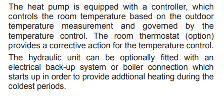
Hello, i live in France, i have a heatpump that was installed by my housebuilder. (Atlantic alfea extensa duo). I have underfloor heating in half of my home (living area), and radiators in the sleeping end.
I am on a very tight budget, and looking to increase efficiency in my radiators. They were all fitted with TRV’s and i cannot see any other type of valve. They seem to have seperate branches for each radiator, but i am not 100% sure on that. but obviously they all join up before returning to the unit.
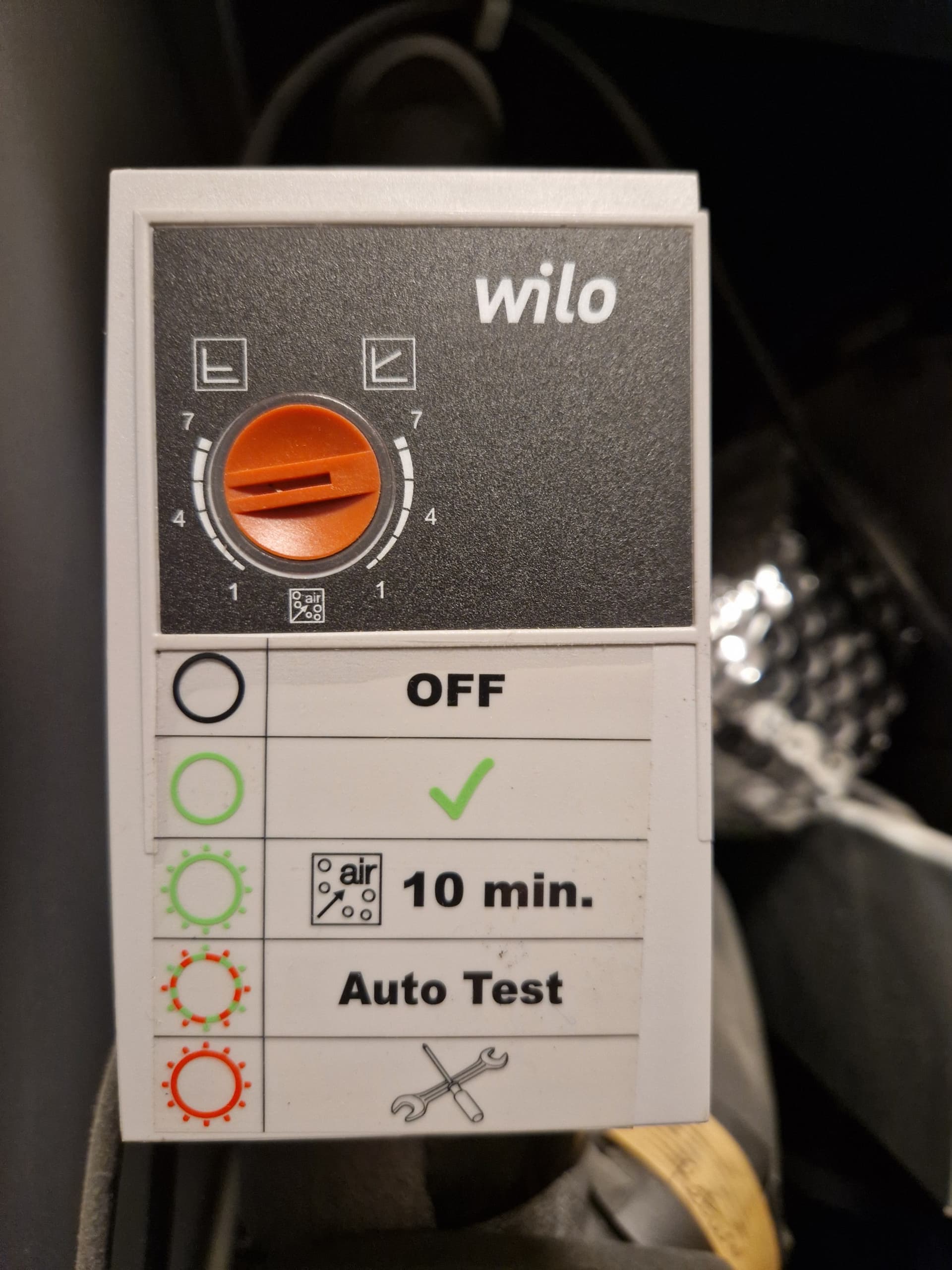
The ASHP has 2 zones, and hot water circuit. The pumps are made by wilo, and they can be switched between constant and variable mode.
The TRV’s have been used to set the temp of each bedroom for several years, and through reading on this forum, i am starting to see that this might be sub optimal.
I have some outputs monitored in home assistant, and i think i have a delta T for the radiator circuit of about 10 degrees, i cannot currently measure power consumption or flow rate.
Could anyone help me understand what approach i should take to improve? Is it a case of opening the trv’s as much as possible and then closing slightly to balance and then reduce flow rate?
Are your rooms warm enough? Too warm? How is the heatpump control configured?
Keeping the TRVs open is generally recommended, setting them only to prevent rooms overheating in case of solar gain. Reducing the volume of the system will push up the required flow temperature, and result in more cycling of the heat pump.
Running everything as a single zone may be better, if you can work out how.
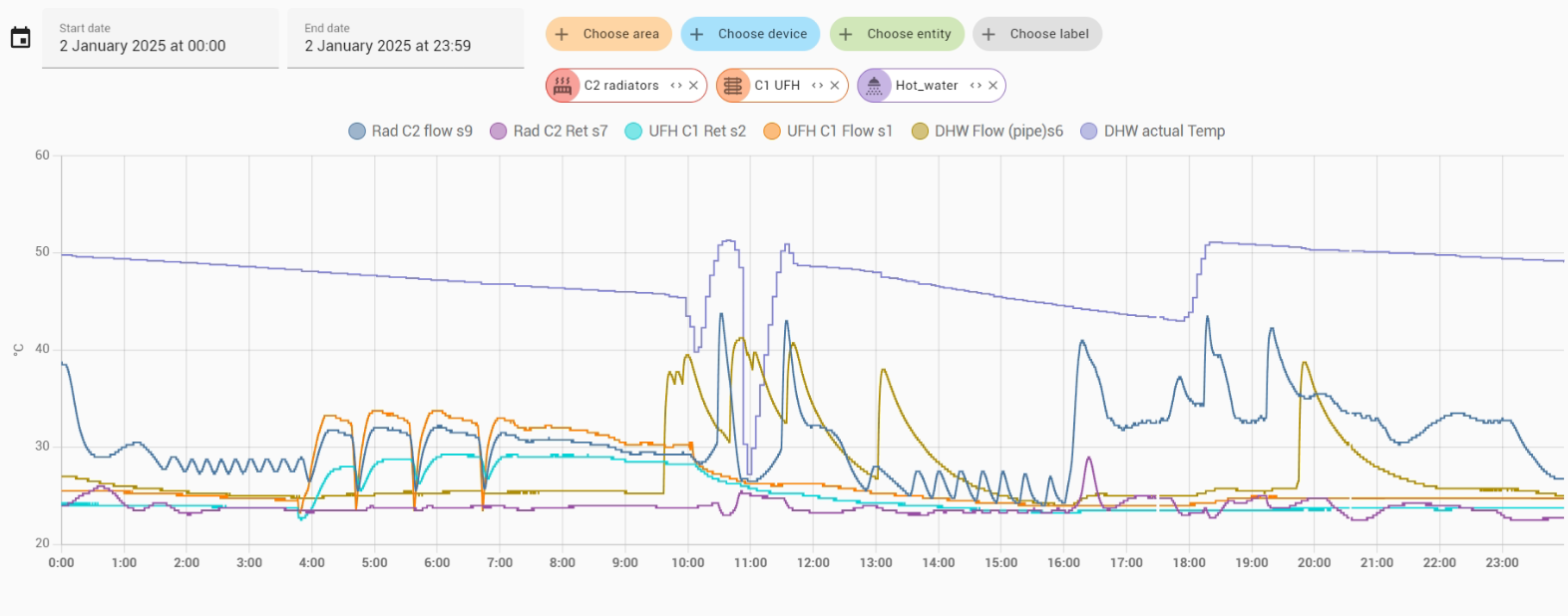
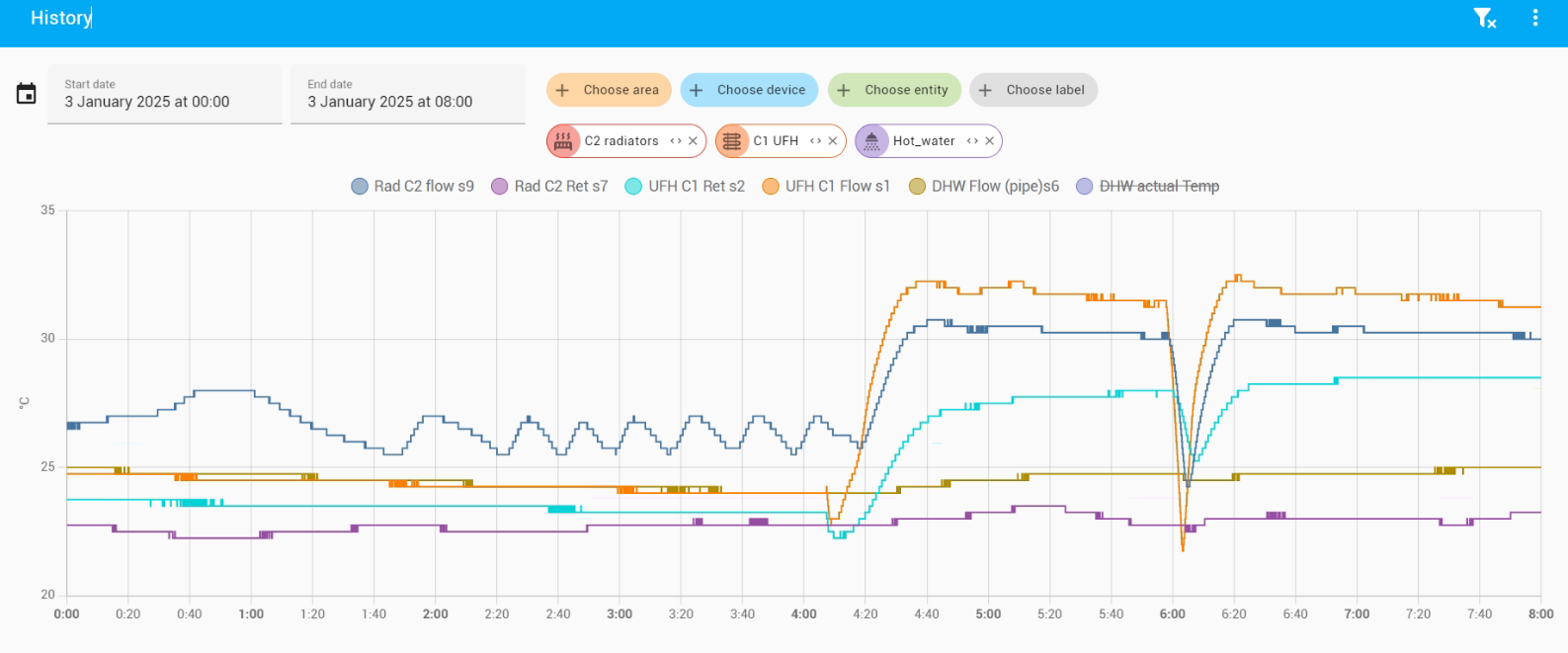
Some graphs of flow temperatures over a typical day and hour would be useful to see, if you have them.
Here is a snapshot of midnight this morning until 8am.
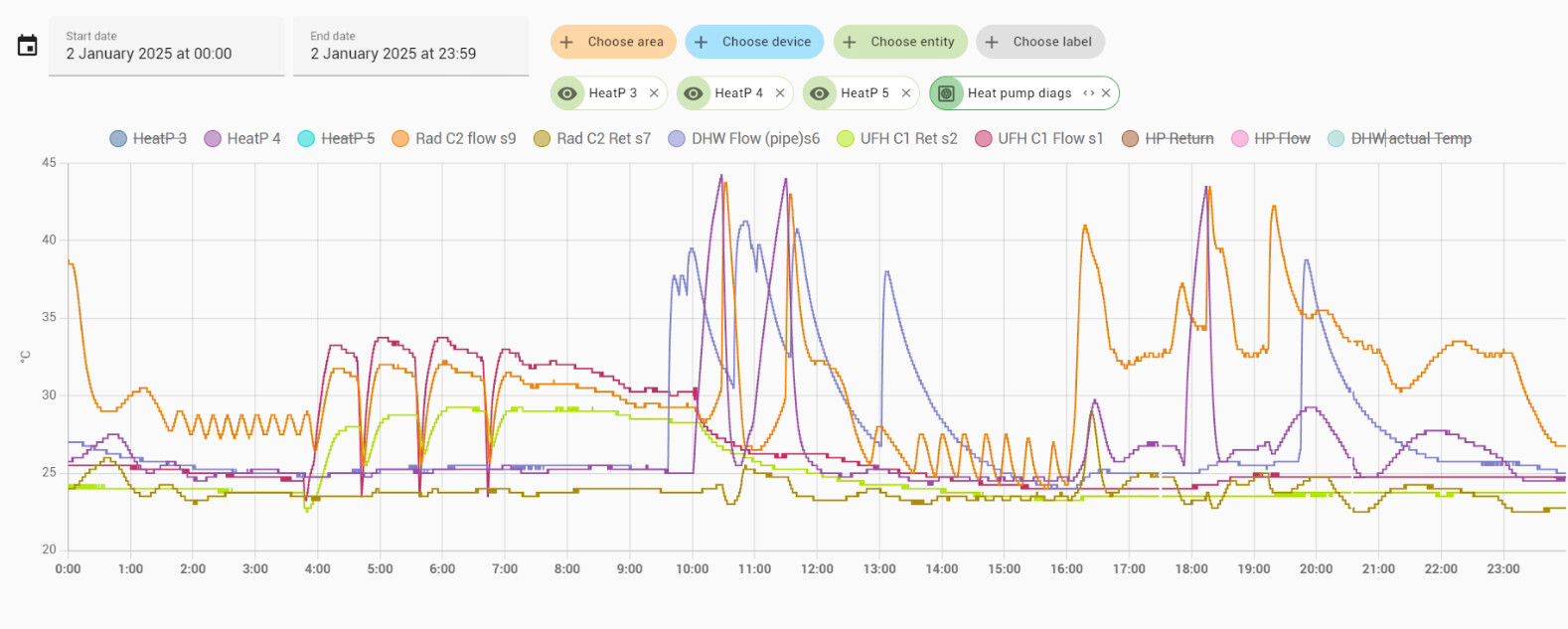
Nervous to hear what you see in these. Let me know if you need more info. or to modify the graphs or include more values. What kind of control info do you want to see? i have a lot of exposed vlaues that i can modify. I will post some later.
This is great to have this type of info, thank you both. I’m really trying to wrap my head around this. It is possible that i have made an error with which pipe is the return. The system is squished into a box, and it’s hard to guess which pipe is destined for what. I will look at my other sensors. guessing from your response about s7 that something more dramatic should be happening more or less in sync with the flow.
Depends how well sized everything in relation to each other. It is possible to size UFH and radiators to run at the same temp but radiators need to be even more oversized etc.
We run everything on the same low UFH temps which works well for us, upstairs bedrooms cooler than downstairs. I think upstairs benefits from downstairs heating a fair amount as no insulation between floors and stairs and balcony fairly open to mix temps.
I’m just confirming 1 by 1 and trying to be sure that my labels are also correct with a mug of hot water. These i can be quite sure are what they say they are. I have added extra insulation to s7 for going forward.
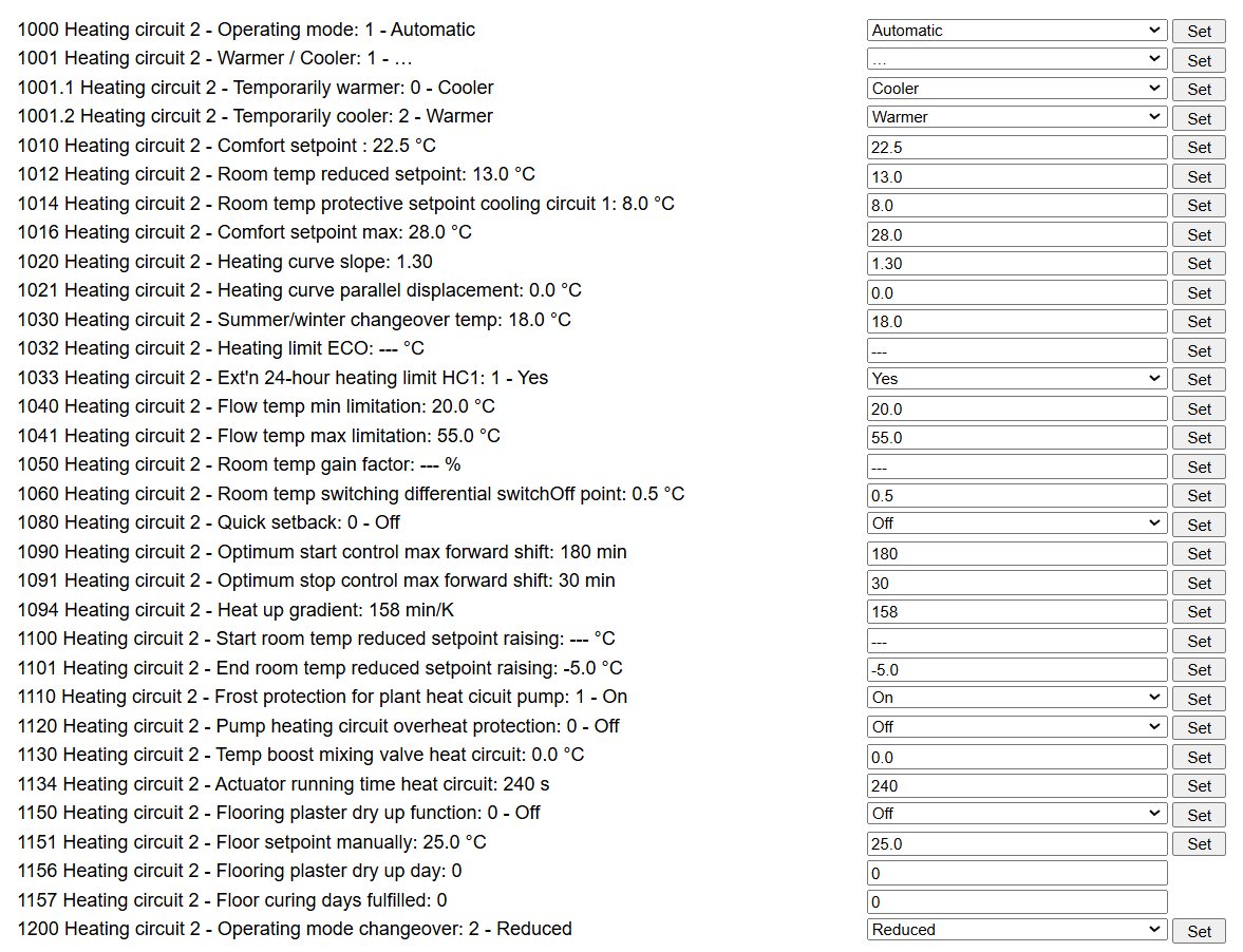
The UFH side is thermostat controlled, i don’t know how the radiator side is controlled. i know that there are sensors for outdoor temperature in the control system. I could only guess weather control… I have this excellent little device installed… https://github.com/fredlcore/BSB-LAN that works for several systems to make the controls accessible.