Help monitoring 2 phases of AC current only ADS1115 & NodeMCU

Hello all,

I have been reading, studying, learning and pulling my hair out for about a week now and am finally at the point where I am totally confused and need to ask for some guidance. Firstly, I’m an electronics tech of over 40 years so the hardware is no problem for me, I have been working with Arduino boards for about 5 years, mainly using others code and modifying to suit my needs so I have basic understanding of code and libraries but I still have SO MUCH to learn, which is why I keep challenging myself with these projects.

Project overview:

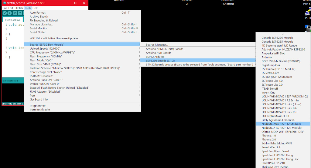
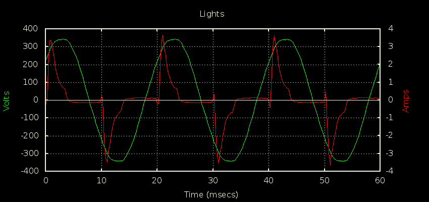
I live in the country and we have frequent power outages, I have 6KW Onan backup genny, old, but reliable. I want to be able to monitor oil pressure, cylinder temp (it’s air cooled) and current of both phases of the 230VAC output so I can balance the loads. (I’m in Canada, 60Hz) I have the temp and pressure working just fine, my problem is measuring the 2 phases of current. Ideally I would like to use the NodeMCU ESP8266 as I have all code written for wifi connectivity for it, and the temp and pressure code, as well as terminal screw breakout boards. From what I have read, although the ADS1115 is slow, it will give reasonable accuracy for current measurement. I’m not concerned with absolute accuracy down to .1A but would like to know what the current loads are on each phase, I don’t need to know power out, if I can incorporate it in the same project however, I will.

I am using the SCT013-000 and burden R of 18R for the 3.3V of the ESP8266 and have it connected in the recommended fashion with equal divider Rs and 10uF cap. Where I am getting fouled up is figuring out how to read and output values from the ADS1115 4 different pins to the serial monitor and ultimately Thingspeak. I would like to use the single ended measurement as I only need 3 analog pins (temp uses MAX6675) I am also having a hard time figuring out the code that works with EmonLib, ADS1115 and the ESP8266. I have tried various sketches from people here and on Github who have apparently made this work but just for a single phase.

I’m not going to post any code here (yet) as I don’t have anything really working properly yet.

After that long dissertation, hope it’s not too much detail, I really just need to get back on track and figure out how to read the 2 current phases.

Thank you all, I look forward to getting over this hump and finishing the project, then I can split and stack firewood and all the 2,324 things I need to do before winter.

kind regards,

Paul

PS if I can move the analog pressure sensor from A0 to the ADS I’d like to do so.

Welcome, Paul, to the OEM forum.

First, a disclaimer - I’ve never used an ADS1115, nor the ESP8266, so I can’t give you any technical details of how to instruct those to make the reading and how to pass data between each other to be processed. What I can do is give you an outline of how I’d approach your problem, in the hope that an overview is helpful.

First, I presume you’ve got the ‘standard’ North America system, we prefer to think of this as two legs of the same phase, because each leg is the inversion of the other.

The ADS1115’s maximum sample rate is 860 samples per second, to you that’s 14.33 samples per mains cycle. At this rate, you’re limited to using the discrete sample emonLib, and even with that you’re not realistically going to be able to measure voltage and as a result you can’t measure real power. So what you’ll have is a moderately accurate value of rms current, but only a best guess at apparent power, the accuracy of which depends on the combined power factor of your house loads and the voltage you assume. I think you realise this.

In outline, what I would do is the ESP8266 sets up the ADS1115 by telling it which input pin to enable, then commands the ADS to take readings. As the readings arrive (and this is how emonLib works), it counts the number of readings, squares each and adds them to an accumulator. At the same time, it runs a low pass filter to derive the average d.c. voltage so that it can subtract the offset that’s added by those two equal resistors (nominally but never equal to half the ADC full scale number). Having got the required number of samples (which you must calculate so that you get as close as possible to a whole number of mains cycles, you switch the ADS1115 to the next channel and do the same with the other leg.
Now as you’re writing the code (but probably leaning heavily on emonLib), you can then switch the ADS1115 to the third input and (say) read the pressure, to the fourth and read (say) temperature, then drop into the output department and send the values, before going back to the first and get another 200 ms or so of current, and so on.
Obviously, you need different processing for the relatively static third and fourth inputs.

I have no feel for how fast code runs on the ESP8266, I’d suggest if you’re up to the challenge you don’t use the digital low pass filter in emonLib, but instead do as emonLibCM does (because it avoids the relatively slow division in the maths), and this is first, remove the nominal value of the offset (just to keep the sum squared smaller). Then, calculate the sample squared and accumulate this and the sample itself (minus offset now - I call this the sample ‘delta’ - a small change). When you have the totals for the batch of samples, get the average and then (this is the slow part but you’re no longer gathering samples, so it doesn’t matter so much) remove the offset that remains and do the (very slow) square root to get the true rms value using the equation:

     rms of a signal plus an offset = sqrt(signal² + offset²)

The offset in the line above is the average of all the samples (hopefully small and close to zero) and (signal + offset)^2 is the other value you accumulated. The quantity you want out of the equation is “signal”. Rearrange the equation, and remember you also need to divide by the number of samples, so

      Irms = sumSampleSquared / sampleCount;
      Irms -= sumSampleDeltas / sampleCount * sumSampleDeltas / sampleCount; 
      Irms = sqrt(Irms);
      Irms *= amplitudeCal;

to give you amps.

I wouldn’t try to use emonLib directly because it was written for the Atmel ATMega328P, you’ll probably be totally confused because it is very closely tailored to that. Rather, understand just the small part I’ve outlined above and steal snippets as you need them.

Thank you Robert, for the warm welcome, your response is very much appreciated. I know from reading this forum and a few others on the web, that you are indeed the master of EmonLib and measuring energy and working with all of the Arduino modules.

Yes, I’m in Canada, standard 240VAC 60Hz dual leg 120VAC with neutral.

I decided after I posted, to just start from scratch and have a single channel of current monitoring working with the ESP8266 single 10 bit A0 input, which is fine and is working perfectly. The ESP unfortunately has only one Analog in pin which is why I am using the ADS1115, which came with my SCT-013 CT. BTW, the ESP8266 has an 80MHz processor, I think the 328 is 16MHz?? It’s the ADS1115 which is limited to 860s/s, I may have to move to the ADS1015 which is capable of 3,300 s/s or incorporate your method suggested. It’s going to take me a few read throughs to digest it all but I should be able to make it work. It would be nice to have power displayed, just as a point of interest.

As I mentioned in my first post I am using the ESP8266 as its wifi implementation and ways to communicate with the outside world seems much simpler than using the ESP-01 with an UNO or Nano, clunky AT commands and many lines of code needed. (unless I am unaware of other ways of using the ESP-01 with the UNO etc.) That said, I would certainly entertain going back to an UNO or Nano, I have many of both, and use the EmonLib and already perfected ccts published on this site. I would just need to modify some of the code to work with the MAX6675 for temperature and add the usual pinmode lines etc.

I’m going to reread your suggestions and contemplate this for a while, ultimately I have already learned a lot but would like to, after a week of working on this, avoid any further hair loss. I took today off work so I could focus on a solution and get it nailed.

I appreciate your guidance.

Thank you.

Paul

Hello and welcome aboard, Paul.

If you haven’t already read it, have a look at this thread:

1 Like

Hi Bill, Wow! Another guru stepping in to help me, thank you!

Yes, I saw that thread a few days back, I’ll revisit it again as I now know a little more than then, and may comprehend it better.

I went down two roads today, both with moderate success, well actually good success but with more work still required.

I went back to a Nano and redid the code using EmonLib and have it reading 2 phases of current, quite accurately, well good enough for my needs and am happy with that, but then came getting it out to the internet, Thingspeak. I have used the ESP-01S before but AT commands (insert bad word here) are atrocious and awkward, and I’d need a 3.3 regulator to run it…you get the idea. I don’t like the combo.

So out came the ESP8266 NodeMCU again, and got some code working and compiling without errors, it’s outputting 0 but it’s more than I had yesterday and I have yet to actually connect the ADS1115, but at least the MCU isn’t crashing (yet…).

If I get rained out again tomorrow I’ll be back at it and hopefully the ADS1115 won’t cause a crash.

I really don’t need to get this working, I mean the genny will run just fine without me knowing what’s going on, but being an electronics tech who now moves dirt for a living, this project gives my brain something challenging to do, and with my status soon to change to “senior”, it’s a great exercise.

Thanks again for the help.

cheers

I am reading this epic thread now, 178 replies, could take a while to read it all but in the first few posts I am reminded of the slow speed of the ADS1115, I now have some ADS1015s on the way, 3300 s/s vs the 860 of the ADS1115.

cheers

Do you know about the emonESP? It’s an emonTx (same processor as the Arduino Uno) with an ESP8266 attached and the ESP pre-programmed for our data output format to Wi-Fi, and it is available from the shop, or get the code from Github and tweak at your leisure.

Can definitely relate to that.
My ET career ran from 1974 to 2020. Now that it’s a “full time” hobby, I’m enjoying it more than ever.

And jumping on the bandwagon, I collected my 50 years of membership badge of the IEE (now the IET) a few years ago. :smiley: I joined in 1968 as a student apprentice.

No, I haven’t looked at it yet, but I will now, thank you, and I’ll checkout the Github source as well.

Thanks

Well some more progress today. I managed to get the ADS working properly with the ESP8266 and calibrated very closely to my Fluke clamp meter.

Now I need to ask for some help please with the code to make it 2 channel. I thought I had it ready to go, took about 20 minutes of compiling and making little changes then recompiling to where I had it compiled but then crashed when it was about to upload. I’ve put the code back to single channel so as not to muddle it up.

Could one of you wizzy Arduino code writers help me get this working with 2 channels please? I am not sure which variables need to be set for channel 2. I can read the ADS1115 channel 2 no problem, it’s the math functions that are confusing me. I can’t take credit for the math part of the code, as suggested, I found something that worked for the current measurement in single channel and used that.

Thank you.

Paul

#include <ESP8266WiFi.h>
#include <Wire.h>
#include <Adafruit_ADS1015.h>

Adafruit_ADS1115 ads;  

double offsetI;
double filteredI;
double sqI,sumI;
int16_t sampleI;
double Irms;
double squareRoot(double fg)  
{
  double n = fg / 2.0;
  double lstX = 0.0;
  while (n != lstX)
  {
    lstX = n;
    n = (n + fg / n) / 2.0;
  }
  return n;
}

double calcIrms(unsigned int Number_of_Samples)
{
    float multiplier = 0.02F;    
  for (unsigned int n = 0; n < Number_of_Samples; n++)
  {
    sampleI = ads.readADC_SingleEnded(0);

  //  Digital low pass filter extracts the 2.5 V or 1.65 V dc offset, 
  //  then subtract this - signal is now centered on 0 counts.
    offsetI = (offsetI + (sampleI-offsetI)/1024);
    filteredI = sampleI - offsetI;
    
    // Root-mean-square method current
    // 1) square current values
       sqI = filteredI * filteredI;
    // 2) sum 
       sumI += sqI;
  }
  
  Irms = squareRoot(sumI / Number_of_Samples)*multiplier; 

   //Reset accumulators
       sumI = 0;
//--------------------------------------------------------------------------------------       
 
  return Irms;
}

void setup() {
  Serial.begin(9600);
  delay(10);
  ads.setGain(GAIN_ONE);        // 1x gain   +/- 4.096V  1 bit = 2mV      0.125mV
  ads.begin();
}

void loop() {
     
  double current = calcIrms(1480);
  Serial.print(Irms); 
  Serial.println("  ");
   
}

And in case anyone is interested… my ThingSpeak channel streaming real time data. Temp and oil P sensors are not connected, current is monitoring my power bar for my computer desk, lights etc. I’m feeding both current phases from channel 1 until I get 2 channels reading correctly in the ESP8266.

cheers

Thing Speak Generator Monitor

I prefer to teach you how to get to the answer, rather than telling you outright. So…

  1. What is the equivalent statement to read the second channel?
  2. Change calcIrms(...) so that you can tell it which channel to read, no.1 or no.2
  3. In loop extend it to call calcIrms(...) twice, once for each channel, save the result separately as (say) currentA & currentB for the A & B legs and then print the results.

Hint: to solve the puzzle of what you need to do for point no.2, you do for ‘readADC’ exactly like the way Number_of_Samples [ = 1480] gets from double current = calcIrms(1480); all the way to for (unsigned int n = 0; n < Number_of_Samples; n++) [as well as, not instead of Number_of_Samples].

If you struggle, come back with your best attempt.

Thank you Robert,

I agree, it’s the best way to learn. I will come at it with a fresh brain and try it again. I thought I had it ready to go once, I know how to retrieve the data from each pin and assign xxx1 and xxx2 for each input and variables, I just had a tough time figuring out what had to have 2 separate formulas for each channel and what could remain a common between the channels.

First cup of coffee is in hand, the fire is lit…and away we go.

More later.

Paul

1 Like

Ok, two cups of coffee later and some more hair loss, I’m back to it compiling as it did yesterday but crashing right at the end. Here’s my code and then the error message.

Thanks again. I am still right at the beginning of the code learning curve and understanding the C++ language, hardware is my strength. :face_with_diagonal_mouth:

#include <ESP8266WiFi.h>
#include <Wire.h>
#include <Adafruit_ADS1015.h>

Adafruit_ADS1115 ads;  

double offsetI;
double filteredI;
double sqI,sumI;
int16_t sampleI1;
int16_t sampleI2;
double Irms1;
double Irms2;
double squareRoot(double fg)  
{
  double n = fg / 2.0;
  double lstX = 0.0;
  while (n != lstX)
  {
    lstX = n;
    n = (n + fg / n) / 2.0;
  }
  return n;
}

double calcIrms1(unsigned int Number_of_Samples);
double calcIrms2(unsigned int Number_of_Samples)
{
  /* Be sure to update this value based on the IC and the gain settings! */
  float multiplier = 0.02F;    /* ADS1115 @ +/- 4.096V gain (16-bit results) */
  for (unsigned int n = 0; n < Number_of_Samples; n++)
  {
    sampleI1 = ads.readADC_SingleEnded(0);
    sampleI2 = ads.readADC_SingleEnded(1);


  //  Digital low pass filter extracts the 2.5 V or 1.65 V dc offset, 
  //  then subtract this - signal is now centered on 0 counts.
    offsetI = (offsetI + (sampleI1-offsetI)/1024);
    filteredI = sampleI1 - offsetI;
    
    // Root-mean-square method current
    // 1) square current values
       sqI = filteredI * filteredI;
    // 2) sum 
       sumI += sqI;
  }
  
  Irms1 = squareRoot(sumI / Number_of_Samples)*multiplier; 
  Irms2 = squareRoot(sumI / Number_of_Samples)*multiplier; 
  
   //Reset accumulators
       sumI = 0;
//--------------------------------------------------------------------------------------       
 
  return Irms1;
  return Irms2;
}

void setup() {
  Serial.begin(9600);
  delay(10);
  ads.setGain(GAIN_ONE);        // 1x gain   +/- 4.096V  1 bit = 2mV      0.125mV
  ads.begin();
}

void loop() {
     
  double current1 = calcIrms1(1480);
  double current2 = calcIrms2(1480);
  Serial.print(Irms1); 
  Serial.println("  ");
  Serial.print(Irms2); 
  Serial.println("  ");
   
}
Arduino: 1.8.8 (Windows 7), Board: "NodeMCU 1.0 (ESP-12E Module), 80 MHz, Flash, Disabled (new aborts on oom), Disabled, All SSL ciphers (most compatible), 32KB cache + 32KB IRAM (balanced), Use pgm_read macros for IRAM/PROGMEM, 4MB (FS:2MB OTA:~1019KB), 2, v2 Lower Memory, Disabled, None, Only Sketch, 115200"

c:/users/t500 daddy/appdata/local/arduino15/packages/esp8266/tools/xtensa-lx106-elf-gcc/3.1.0-gcc10.3-e5f9fec/bin/../lib/gcc/xtensa-lx106-elf/10.3.0/../../../../xtensa-lx106-elf/bin/ld.exe: sketch\Current_Monitor_2_Channel_Working.ino.cpp.o: in function `setup':

C:\Users\T500DA~1\AppData\Local\Temp\arduino_modified_sketch_298347/Current_Monitor_2_Channel_Working.ino:63: undefined reference to `_Z9calcIrms1j'

c:/users/t500 daddy/appdata/local/arduino15/packages/esp8266/tools/xtensa-lx106-elf-gcc/3.1.0-gcc10.3-e5f9fec/bin/../lib/gcc/xtensa-lx106-elf/10.3.0/../../../../xtensa-lx106-elf/bin/ld.exe: sketch\Current_Monitor_2_Channel_Working.ino.cpp.o:(.text.loop+0x18): undefined reference to `_Z9calcIrms1j'

collect2.exe: error: ld returned 1 exit status
exit status 1
Error compiling for board NodeMCU 1.0 (ESP-12E Module).

You’re duplicating far, far too much.

Very little.

Almost everything.

Here’s my take on point 2:

double calcIrms(unsigned int Number_of_Samples, byte inputChannel)
// A byte is unsigned, 8 bits wide. You'll only ever need 2 bits here (inputs 0-3)
{
  float multiplier = 0.02F;    
  for (unsigned int n = 0; n < Number_of_Samples; n++)
  {
    sampleI = ads.readADC_SingleEnded(inputChannel);

    //  Digital low pass filter extracts the 2.5 V or 1.65 V dc offset, 
    //  then subtract this - signal is now centered on 0 counts.
    offsetI = (offsetI + (sampleI-offsetI)/1024);
    filteredI = sampleI - offsetI;
    
    // Root-mean-square method current
    // 1) square current values
    sqI = filteredI * filteredI;
    // 2) sum 
    sumI += sqI;
  }
  
  Irms = squareRoot(sumI / Number_of_Samples)*multiplier; 

  //  Reset accumulators
  sumI = 0;
  //--------------------------------------------------------------------------------------       
 
  return Irms;
}

Compare that with your original in post no.11, NOT the crashing version.

Only when you understand how and why this will work, look at point no.3

[How far from UTC are you? I’m off to cook a meal, back in a couple of hours.]

Thank you Robert!

It’s 9:48am here, enjoy your dinner.

I’ll go back to it shortly, I need to clean the workbench so I can build this into a box once I get the code working…hopefully today. :slight_smile:

Cheers

Silly question, but I’ve been bitten by this one…

Is your “board” selection set to NodeMCU?

e.g.

If you get back to this by 4pm your time, I’ll probably still be around. Otherwise, it’s tomorrow.

Meanwhile, I’ll try to point out and explain the things you got wrong, and the things I’d do differently.

1. You wrote that you wanted to use emonLib. The way this works is it samples a channel (both voltage and current if you want power, or just the current if you only want current) for a fixed period of time. In the case of power, voltage is available so it can count mains half-cycles and start and stop as close as it can to a zero crossing. In the case of current only, you have to calculate (or measure) and give it the number of samples to record so that you’re as close as you can be to a whole number of mains cycles, otherwise, the rms average will be wrong because of the extra part-cycle – and you can’t define the starting or ending points, so the error is essentially random. Having sampled one channel it switches to the next, and so on. When it’s done all, it dispatches the data to wherever it’s needed. Then the sketch waits (the way we used it) for 9 s or so and then tells it to get the samples for all the channels again.

2. Now, looking at loop(...), you think you’ve got two functions to get the current. In fact you haven’t, because you’ve both declared and defined only one – double calcIrms2(unsigned int Number_of_Samples) { ... }. You declared double calcIrms1(unsigned int Number_of_Samples); but that’s all, there is no definition of what it does – there is no pair of curly brackets with code between them that defines how it does anything.
This is what "undefined reference to _Z9calcIrms1j "is trying to tell you (but the name has got mangled).

3. Inside calcIrms2(...), you’re trying to sample both samples sequentially. This would be OK, but (a) it’s not how emonLib works and more seriously, calcIrms2(...) is defined as returning a double – A double, one, not two, so

  return Irms1;
  return Irms2;

is illegal because you can never return two separate things from a function. To do this, you’d have to either use global variables (these are values that exist for all time all over the sketch, which is messy and generally not recommended) or you’d need to use an array or pointers, and that’s probably too advanced for you at the moment.

The other, and best, reason for not doing both legs in parallel is your sample rate from the ADS1115 is slow, 860 samples per second, to you that’s 14.33 samples per mains cycle. If you’re doing two channels, that’s only 7.167 samples per cycle. You’ll be in trouble if there’s anything above the third harmonic in your current wave. If you have a current wave like this spiky current waveform (Washing machine brushless d.c. motor on spin by @dBC

Phase measurement and correction in IoTaWatt - #17 by dBC)

or this most distorted channel made up of a boat load of CFLs:

(from The importance of continuous sampling Red is the current, also thanks to @dBC)
Just consider how much of the wave you’ll sample, or not sample, with only 14 - let alone just 7 sampling points - on each cycle.

1 Like

Hi Bill,

Yes I have run into that before in a “seniors moment” but not this time. ha! Thanks for the thought though.

Robert, thank you for the detailed reply, I haven’t read it yet, I had a bit of a mental meltdown and realized I shouldn’t be learning Arduino code right now with so much to do before winter hits. It’s the sort of thing I should be doing in the dead of winter when there is 3’ of snow on the ground and there’s nothing to do. I really need to take a course or get a book and really learn C++, it’s not something I think I can pickup and make useful right now. I have been successful in the past with various projects but that was more cut and pasting things into a sketch and making it work, I actually have never really written complex code from scratch, there’s my confession, I’m a hardware engineer.

I will let you know when I make more progress on this, it could be a few months or if I get things done that need doing, I may get back on it right away, either way, I WILL figure it out, come hell or high blood pressure.

Cheers and thank you both so much for the guidance.

1 Like