So, I am trying to use a YHDC SCT-013 to read a current from my mains supply. I have Solar power, and ultimate aim is to measure when net overall usage < -3Kw and turn on the immersion heater. SCT device attached around the thick Live (brown, UK) cable
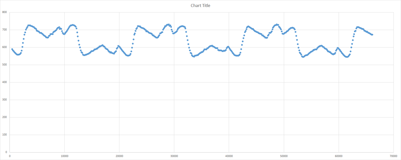
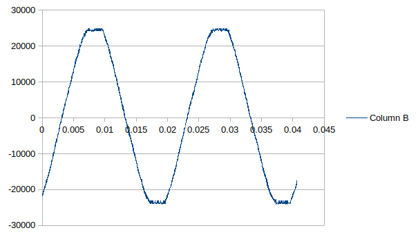
The results were a bit unreliable, so I have sampled the analogue reading and plotted it here (x-axis is microseconds, y is A0 reading). my concerns:
1 - not centred on 512
2 - not a smooth curve
have i done something stupidly wrong?
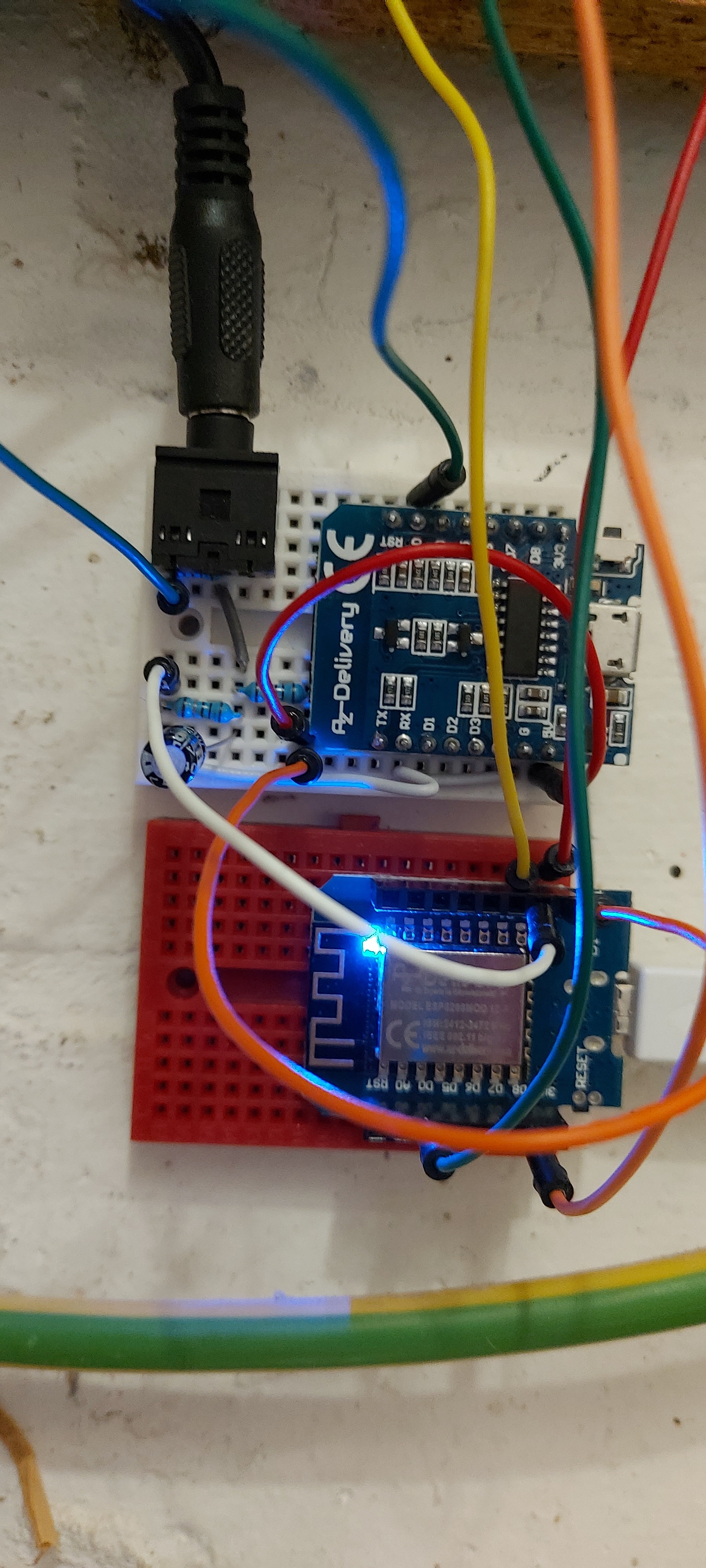
the circuit is the top board in the picture. 5V across a voltage divider, 33ohn burden resistor
Are you sure you’ve connected the c.t. correctly? The current appears between tip and sleeve of the plug. That trace looks more like noise or stray AC pick-up than anything else.
I’m guessing you are using our emonLib and one of our example sketches. What is the hardware that you’re using? EmonLib was written specifically for the Atmel ATMega 328P, so it’s probable that there will be things that need changing to make it work correctly with anything else.
Please take a moment to look at our FAQ page. That might give you some hints about how you can make it easier for us to help you.
Running on a ESP-8266, but with my own code to extract the raw analog readings. Ill take another sample at night, so the solar is off and can then check against the meter
(Hint: the plug goes in from the left. The tip is the furthest away from the sleeve. Or you could measure with a multimeter - the secondary winding of a SCT-013-000 is about 100 Ω.)
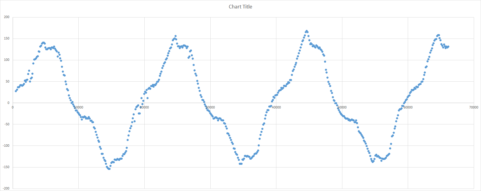
the connections were OK, but I think the sensor was too close to the neutral cable - I moved them to be a couple of inches apart and getting much nicer looking readings. I was kinda expecting a beautiful smooth sine curve, but I guess mains electricity isn’t going to be the smoothest signal
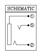
That still isn’t what I’d expect from a 3 kW immersion heater. I’d expect something much closer to a sine wave, but with flattened peaks.
OK, that’s from a digital 'scope, but that’s the shape to expect in the UK. I’d expect your immersion heater to give you that with a peak-peak amplitude of approx. 180 counts, assuming a 10-bit ADC and a 5 V reference.
That should make no discernible difference. If it does, you’re not measuring the current - or rather, you’re measuring current plus something else.
There are two modules in your photo, so you’re using something else as well as the ESP8266. What is the one without the blue LED?
If you want us to help you, can we have a real circuit diagram? One with pin functions labelled and component values (because I can’t see the colours on the resistors (they look like 180 Ω, which I don’t believe), and I can’t see where wires go off the picture.