We’ve had a F2040 with SMO S40 since Nov 2023, and we have UFH on ground and 1st floor with rads on the 2nd floor which were installed at the same time. It’s a semi-detatched house, build approx 1948, with new windows throughout. The loft conversion is recent, along with a ground floor extension, and we had cavity wall insulation fitted in the remaining original external walls. So while the insulation level isn’t amazing, it’s as good as we can get for now. The UFH is managed through two manifolds (1GF 1FF) and individual room thermostats.
The system had been working fine until just after Christmas - don’t know how optimised it was, but it hadn’t done anything to warrant further inspection given that I also have a job and a toddler!
Just after Christmas we lost pressure and the installer came out to look. A washer had failed on a small circulation pump, which they replaced and got the system back up. However, we have since had continual issues. The most apparent was short cycling every time it tried to heat the DHW, to the extent that we have now switched the direct electric immersion on full time so that the heat pump doesn’t ‘see’ the DHW load. The installer believed this was due to air getting in when the pump washer was replaced, but multiple attempts (by them and us) to bleed the air out have not resolved it.
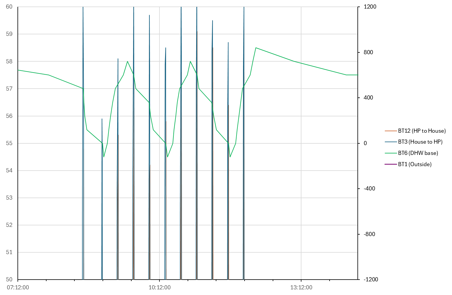
In addition to the DHW issue, it is now running defrost cycles every 20 minutes, which means we aren’t actually in ‘heating’ mode long enough to supply the heating demand from the house, and the degmin is getting steadily more negative. I’ve also noticed that every time it runs a defrost cycle we lose 1-1.5deg from BT6 - this suprised me as I wouldn’t have thought BT6 would be impacted by the defrost cycle. The defrost cycles also cause BT12 and BT3 to spike up to >55degC, and in some cases we get an error on the system and it shuts down until we reset it.
The installer is aware and is hopefully coming out to look early next week, but I wanted to know what questions I should be asking or if this is expected behaviour?
If it is helpful, we are on curve 11 (set by the installer) and have tried offsets between -1 and +2 but we can’t tell how they compare for comfort while the system is defrosting so frequently.
Happy to share graphs - I am having to manually download from the web version of myuplink for graphing in excel and the variables in there are a bit more limited than I’d like.
This is the correlation between BT6 (green), BT12 and BT3 when the defrost cycles are happening. This is with the electric immersion on fully, so I don’t see why the defrost cycles are having any effect on BT6.
Another new NIBE owner; welcome! Thanks for describing your situation so well. (Note I took the liberty of adding “NIBE” into your post title to help those readers not familiar with the model numbers.)
I have a NIBE system but it’s Ground Source so I personally have no experience of NIBE Defrost cycles and I’m hoping some NIBE ASHP owners will chip in. Defrosting every 20 minutes surely can’t be right though.
Like you, I would not have expected the BT6 (DHW Cylinder Temperature Sensor) to show any change during a Defrost cycle - but another NIBE owner recently reported they have been seeing ‘tank defrosts’ which sound broadly similar (see NIBE ASHP and tank defrosts).
From everything you’ve described, I get the impression that the recent work by your installer has resulted in some sort of fault, perhaps due to reduced flow somewhere. It seems particularly odd that DHW heating isn’t working properly, since that’s much ‘simpler’ than space heating, with shorter pipe runs - albeit generally at a higher temperature - and none of the complexities of WC Curves or Degree Minute control.
I’d recommend double-checking that none of the valves got closed or wiring dislodged during the recent work (though I’d have hoped your installer would have checked that already):
Does the ‘Charge Pump’ circulation pump cabling look OK? Is that pump running?
Does the DHW ‘Diverter Valve’ (typically has a red plastic cap) cabling look OK? Can you see the indicator that shows whether that is pointing the right way for DHW or Central Heating?
If your Degree Minutes are getting steadily more negative there’s nothing to be gained by tweaking the Curve or its Offset. The too-frequent Defrosting will be the cause of that.
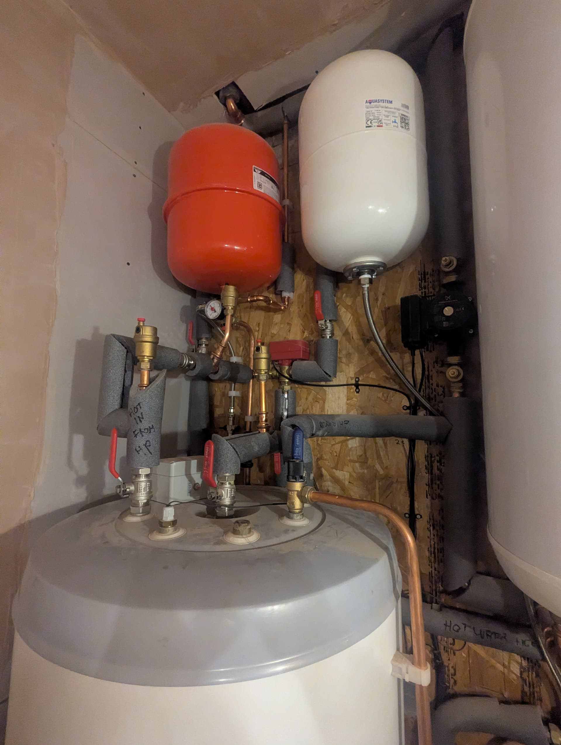
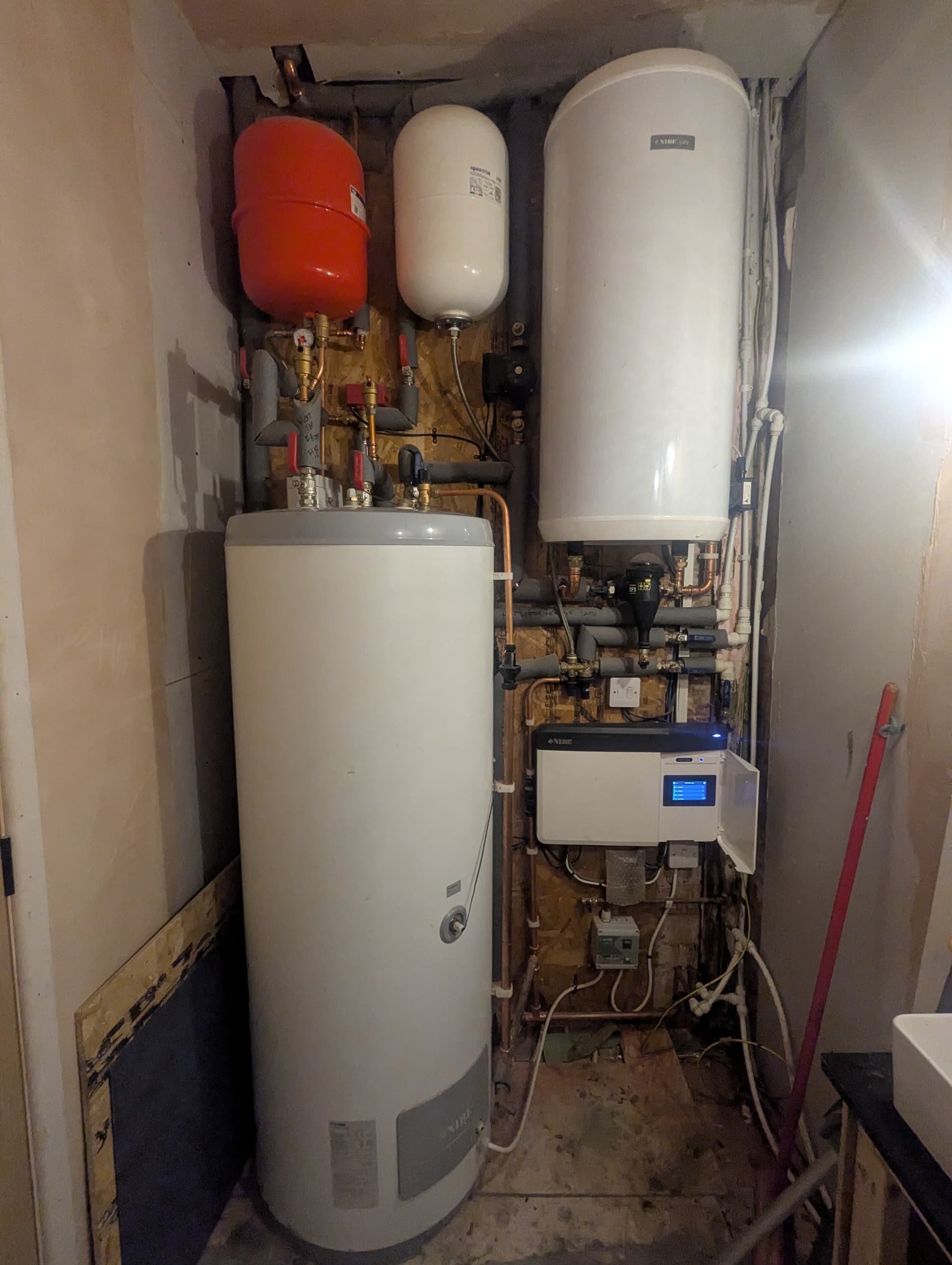
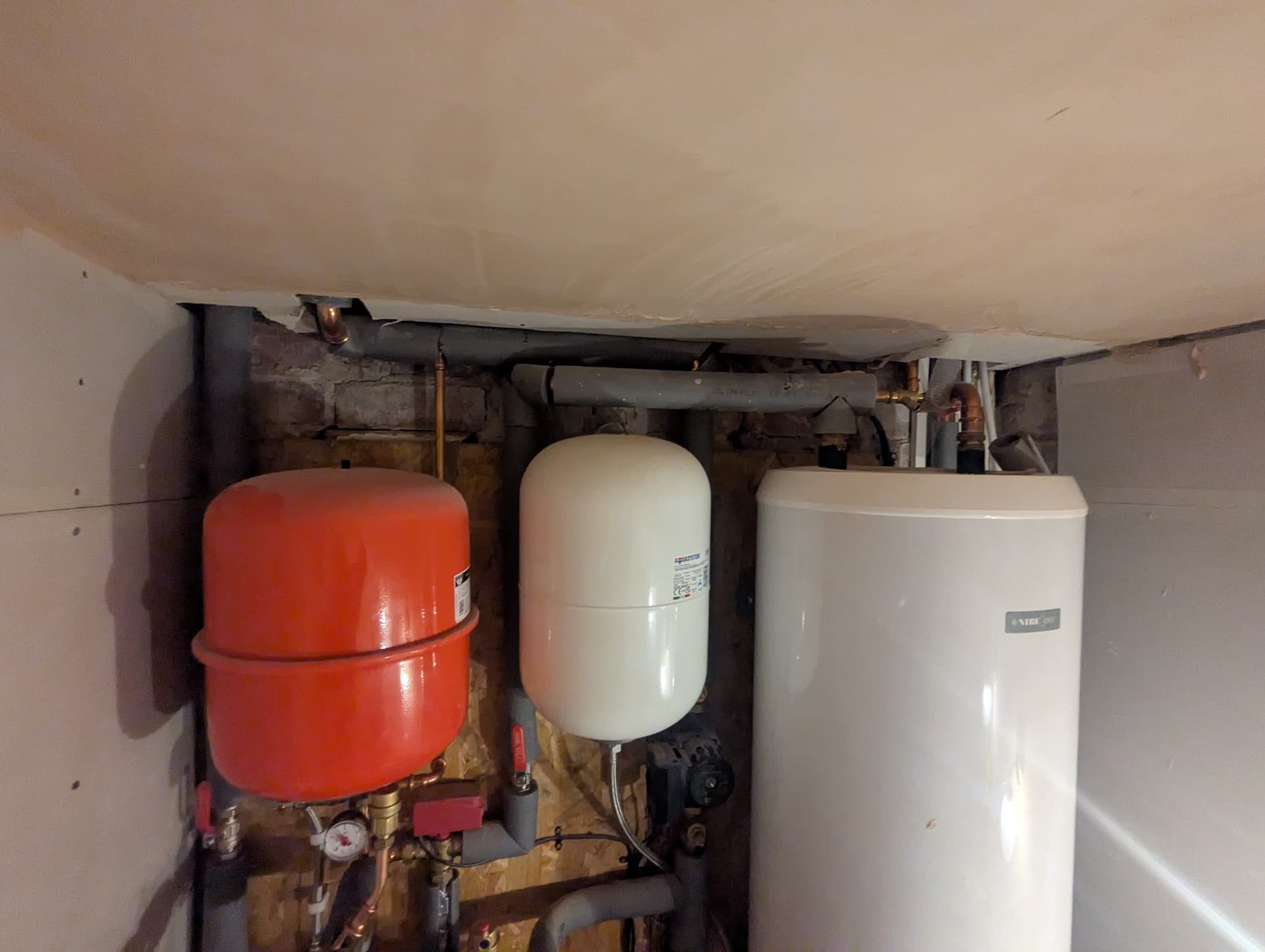
If you are able to post of a photo of the indoor pipework that would be useful context.
All the valves appear to be open and I can’t see anything that looks to be loose or dislodged. I’ve attached some images below. I think I’ve managed to follow through most of the pipework and valves.
It seems like tank defrosts would explain a lot of what we’re seeing - thanks for the suggestion. They would cause BT6 to drop slightly, as cold water from the heat pump is brought through the cylinder coil to be warmed up.
Also at the start of the defrost cycle, the BT3 return sensor will see whatever the current temperature is in the hot water cylinder. In our case, that is 60deg as that is what the immersion is holding the tank at. I couldn’t work out how BT3 was recording spikes at 60deg during defrosts but that would explain it.
Further, we know there is a flow issue on our DHW circuit, so this is probably still affecting flow when defrosting. This could lead to a failure to defrost fully, and therefore more frequent attempts. Possibly the system is also stopping the defrost early when it sees 60deg at BT3.
I’ll send these thoughts over to the installer and see what they think. Thank you!
Thanks for the photos. It sounds like you are indeed getting ‘tank defrosts’ and if those explain the odd temperature readings you’ve been seeing that’s all pointing to a single underlying issue with reduced/restricted flow somewhere.
One thing that’s not quite clear from the photos is where the pipes from your Outdoor unit connect. The black circulation pump below the white Aquasystem expansion vessel is normally on the Return to the Outdoor unit, so is that the Return pipe heading vertically up above that pump?
The 3-way Diverter valve with the red plastic motor head has to be on the Flow from the Outdoor unit, so the Flow must connect to that valve but its not clear which of the ‘legs’ that is on. The ‘leg’ to the left of the valve is going to the Coil in the DHW tank, so the others are the Flow from the Outdoor unit and the Flow out to the Central Heating circuits. I was under impression the incoming Flow from the Outdoor unit normally went to the ‘middle’ leg, pointing vertically downwards in your case (with some silver tape on the pipe, probably covering a temperature sensor) but it would make more sense if the Flow from the Outdoor unit ran parallel to the Return, coming in from above (via the red-handled lever valve) - in which case the ‘middle’ leg would have to be the Flow out to the Central Heating (and the sensor under the silver tape is probably BT25).
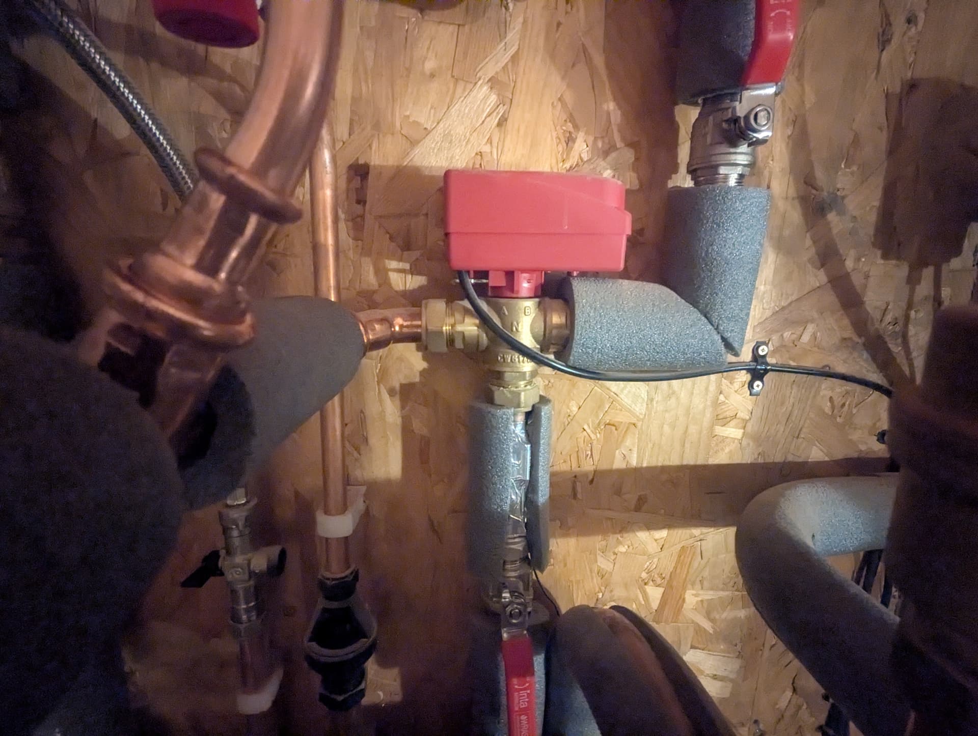
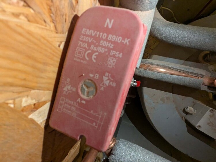
It’s hard to believe things would ever have worked properly if that 3-way valve has the wrong pipe connections but just to confirm it would be great if you could post a close-up or two of that valve showing the printing on the top and any cast markings like A and B on the brass body.
Since the suggestions yesterday, my husband went out to look at the heat pump and found it heavily iced up. We turned off the immersion and ran the taps to reduce the temperature in the HWC in the hope it would allow a defrost cycle to complete. Not been to check the icing level again yet but it certainly tried defrosting for longer than it has recently after that change.
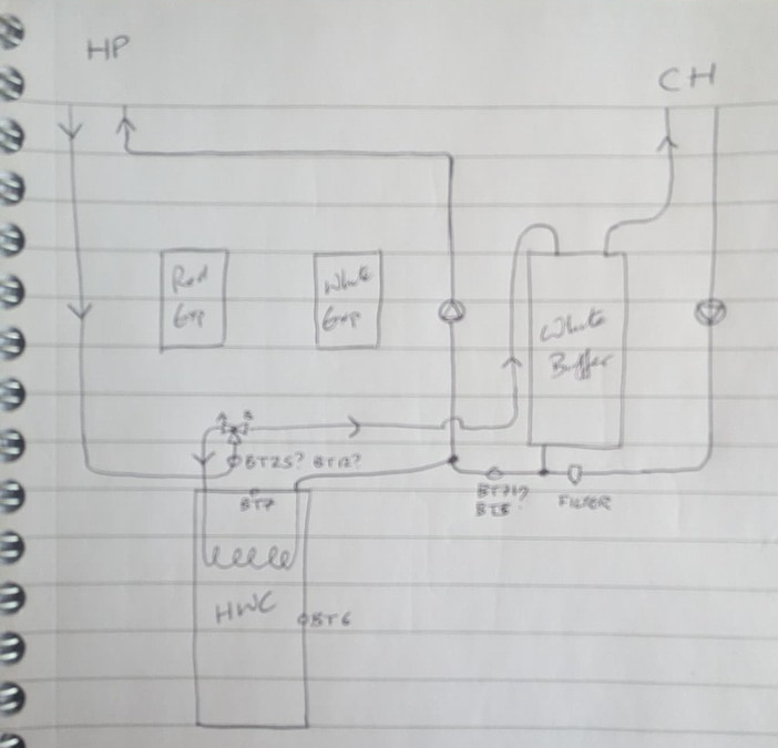
To follow up on your questions. I have done a schematic sketch of how the system is connected up. I’ve not included either of the expansion vessels in this but I can do if needed. I have noted a ‘Fernox TF1’ unit on the return from the CH - I think this is a magnetic filter.
In the far left corner of the ceiling are the hot feed from the HP and the cold return to the HP, in the far right corner are the hot feed to the CH and the cold return from the CH. These all go vertically upwards into the space under our bathroom, before the HP pipes exit horizontally through the external wall to the pump (it is situated on our utility roof). I’ve attached a photo which should show these a bit more clearly.
There are two pumps. The one on the left of the large white buffer tank is on the cold return back to the heat pump, downstream from feeds coming from the CH, DHW and the base of the buffer tank. The second pump is on the cold return from the CH - this is possibly required for our top floor radiators, as the UFH manifolds for GF and FF each have their own pumps.
The hot feed from the HP comes down in the left hand corner, then does a U and comes up to the middle of the red valve, with a temperature sensor just before the valve (BT25? BT12?). The left hand side ‘A’ goes to the HWC. The right hand side ‘B’ goes to the buffer tank, and then a separate pipe exits from the top of the buffer tank to the CH.
I can’t see the labels on the temperature sensors, but there is definitely one under the silver tape just before the valve on the feed from the heat pump, and one under some silver tape on the cold return from the CH just before the DHW return joins (BT71? BT13?).
Thanks for the info (and the edits - that pipework makes more sense now).
The diverter valve is what NIBE call the VST11. There’s a manual for that here. In that manual (and on my older VST11) the ‘middle’ pipe is labelled “A B” but on yours they must have refined that to ‘N’ (on the brass casting; it still says “AB” on the top). So the Flow input from the heatpump goes direct to the bottom of that valve, which is correct.
Normally that valve is set to the ‘B’ direction (Central Heating) but when it’s energised it moves to the ‘A’ direction (Hot Water) - which is what the grey ‘tripod’ indicator is showing in your photo. That tells me the heat pump had actively switched to ‘Hot Water’ mode when the photo was taken - although perhaps that’s what it does during a Tank Defrost. It will be worth checking that the grey disc spins around 180 degrees (to point at ‘B’) when it’s in ‘Central Heating’ mode.
BT12 and BT13 are factory-fitted inside the Outdoor unit so the sensors you can see fitted to your pipework will be BT25 and BT71.
It’s odd to have BT25 on what you’ve confirmed is the input to the diverter valve; that’s meant to be reporting the temperature of the Flow out to the Central Heating side only (not also the high-temperature flow when heating the DHW tank). I doubt that will be contributing to your immediate issues but you’ll get better control long-term with the BT25 sensor moved further down the CH pipework. (There’s normally a specific ‘pocket’ for it under a cover at the top of the UKV Buffer tank, which is where my BT25 is located.)
BT71 sounds to be in exactly the right place; only seeing ‘Central Heating’ Return temperatures.
The Fernox TF1 is indeed a magnetic filter which should trap any corrosion from the radiators, so it’s good to see that included and in a sensible place.
On the Central Heating side, your schematic confirms the UKV is plumbed as a 3-Pipe Buffer Tank. You’ll find lots of discussions on these forums about the pros and cons of Buffers and Low-Loss Headers (which do a similar job) but given you have two UFH manifolds (each with their own circulation pump) and a further pump for the second-floor radiators I’d personally prefer to see a Buffer included since it provides much more predictability of flow directions when 0, 1, 2, or all 3 of the secondary circulation pumps are running (in addition to the primary ‘Charge Pump’ circulation pump).
So apart from tweaking the location of BT25 your pipework all looks good. It’s definitely worth ensuring the Diverter valve is moving between A and B (and checking its wiring connections if not) though.
Was it the circulation pump to the left of the UKV that had the leaky washer? Maybe just double-check the isolating valves immediately above and below that are fully open.
The washer failed on the pump to the RHs of the buffer, the one on the return from the central heating. All the valves on that side appear to be open.
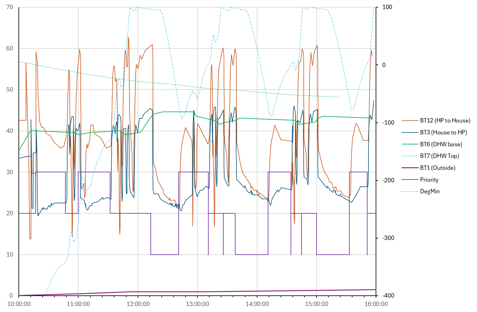
However, I have good news!! Earlier today we ran a lot of hot water out of the DHW tank to bring the temperature to <30deg, then used the immersion to get back to ~40deg and then switched the immersion completely off. The hope was that this would mean it might run a tank defrost successfully, as it would be seeing water at the expected 40-45deg instead of the >60deg that the immersion heats it to. And it seems to have worked!!
The graph below has BT12 and BT3 doing sensible things, without the spikes and crashes we were getting previously. It also shows the heat pump actually heating the DHW (BT6) at about 12:00, suggesting that the flow issues we’d been seeing were maybe all due to failure to defrost successfully. And we now have degmin (RH axis) cycling happily between +/- 100 with about 90mins between cycles. I’m having to track the priority manually, as it is included in the app but not on the website, but that is aligning with the behaviour.
As you note above, with the BT25 sensor upstream of the red valve, degmin is changing whenever the heat pump is on, not just when it is directed to central heating. I will mention this to the installer and ask them to move it.
That’s great news and you’re very welcome. It’s counter-intuitive that the stored hot water in the DHW tank should have been ‘too hot’ for successful defrosting, but you’ve proved that seemed to have been the issue. (I suppose it makes sense for the controller to limit the thermal shock from defrosting given that the evaporator is below freezing when that happens.)
Thinking further about the ideal location for BT25 (and the implications of that seeing the DHW Flow temp in its current location), the intention is for BT25 to track the gradual reduction in Flow temperature around the Central Heating circuit while the heat pump is running a DHW cycle or a Defrost cycle (or is in ‘standby’) - so the controller knows how much of a ‘Degree Minute Deficit’ it needs to make up when it starts the next Central Heating cycle.
Looking at your latest graph around 14:30, the DMs rise to 0 so the compressor switches off (and the DMs start to drop again, as expected) - then a Hot Water cycle starts at about 14:45 so the DMs race up to +100 (where they’re capped by the software). The controller therefore thinks the CH circuit has had lots of extra heat - and delays starting the next CH cycle as a consequence.
Your CH and UFH pumps will be moving water through the Buffer all the time - even during a DHW cycle - so by locating BT25 at the top of the UKV you’d be giving the controller the best view of the Flow temperature actually going into the CH circuit. See what your installer says; if they’re not keen on locating BT25 at the top of the UKV it will be OK as long as it’s on the Central Heating pipe downstream of the Diverter valve.
I suspect you’ll be able to drop to a lower WC curve once BT25 has been moved, since that will be getting a more accurate picture of the temperatures in your CH circuit.
I’d be interested to see an equivalent graph after BT25 has been moved - and of course please post further updates if you still have problems.
A further update to this in case anyone has similar issues.
I increased our curve to shift the degmin lower and try to minimise the amount of time the system is switching off for. This is intended as a temporary measure to correct the effect of the BT25 sensor being incorrectly located. Once BT25 is in the right place we will adjust the curve back down.
This has been reasonably successful - we were seeing it switch off for about 30% of the time even though the UFH was calling for more heat and that’s now down to <10%. I’m also using the immersion (switched manually) to keep BT6 at 40-45C, firstly to minimize the hot water load on the heat pump and secondly to provide warm water for defrosts, without it getting up to 60C where it caused an alarm. We are still getting tank defrosts, which pull BT6 down but they are getting less frequent as the outdoor temperature is rising.
However, even with the system in ‘heating’ mode for most of the time, the house is getting colder faster than the heat pump can supply. I think this is because the buffer tank cooled down a lot when the system was off for the washer failure (BT71 is running at 20C) plus the house is now at 14-16C so the return flow is going to be correspondingly low. A quick estimate suggested the buffer tank would need about 2kWh input to get it warmed up and that’s without any load from the house. Given that all our thermostats are calling for heat and it is still regularly stopping for defrosts, that is obviously hard for it to achieve.
I suspect this low buffer tank temperature may be why the control system has switched to tank defrosts. Unfortunately in our case that combined with an unnaturally high HWC temperature as we had the immersion holding it at 60deg, and this was triggering an alarm which aborted the defrost cycles.
We didn’t experience this issue last year as the system wasn’t off for any length of time and the immersion was in auto, so the buffer tank wouldn’t have cooled down enough to switch it over to tank defrosts and the tank would have been at 40-45 apart from during legionella runs.
I’m hopeful that a bit of warmer weather will reduce the defrost frequency and allow the buffer tank to warm up and correcting the position of BT25 will give the system a better view of the heating load.
Thanks Felicity. That’s a great summary of your consolidated understanding of the situation, why it arose and how the NIBE controller reacted to various conditions (like the too-cold buffer tank and the too-hot DHW cylinder). It’s hugely valuable to have these sort of summaries included for reference by others who read these threads later.
It seems that the weather (in the UK) will be turning unseasonably warm for a couple of days which should help your system get back to normal.
You were unlucky with the timing of your pressure loss, meaning you were trying to heat the house from cold during particularly challenging weather conditions, resulting in lots of defrosting and significantly reduced heat output - exactly when your heating demand was at its highest. That could happen to any of us and it’s a nice reminder that people need to be sizing their systems to (partially) accommodate this sort of ‘cold start’ scenario, not just the much less demanding steady-state running in warmer weather. I’ve commented before that too many people who complain their systems are over-sized only consider the latter, not also the former.