Basic breadboard electricity monitor using the AVR128DB28
First draft: I will probably improve this guide over time, if you have any questions about aspects that are not particularly clear, please ask!
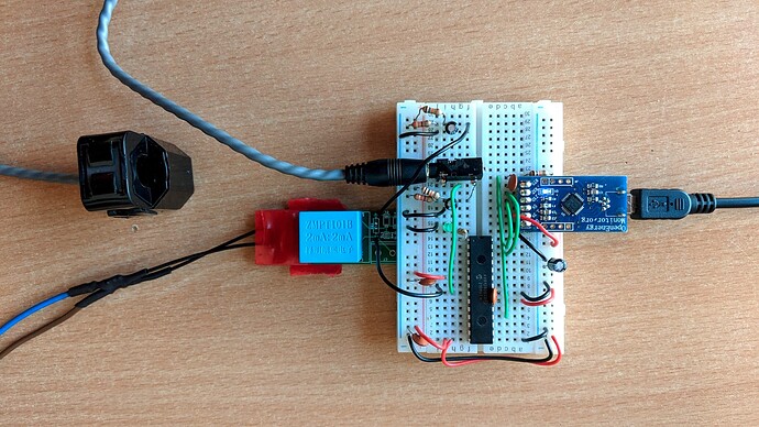
Building on the basic AVD-DB Blink example above, the following circuit adds a voltage sensing channel and a current sensing CT channel. The circuit is very similar to the one documented in our Learn: How to build an Arduino energy monitor page, with one simple voltage divider and decoupling capacitor bias connected a voltage output 333mV CT and another connected to a ZMPT precision voltage sensor (An ACAC adapter could alternatively be used).
Voltage sensing with the ZMPT101
The ZMPT101 precision voltage sensor provides isolation between the mains voltage and the low voltage side. Resistors R1,R2,R3,R4,R5 & R6 below are all 33k resistors and form both a layer of protection in the event of short circuit to one of the resistors as well as forming a voltage divider that reduces the current through the primary down to the required 1-2mA range.
PLEASE TAKE EXTRA CARE IF YOU BUILD THIS CIRCUIT GIVEN THE POTENTIALLY LETHAL HIGH VOLTAGE INVOLVED!! If you have any doubt, please use the AC-AC Adapter approach to avoid handling of any high voltage.
Across the secondary is a 200 Ohm burden resistor providing an RMS voltage output of about 242mV.
This is biased with the simple voltage divider, the top resistor is 18k and the bottom resistor 3.3k, providing a bias of 0.511V, near enough half 1.024V (I am using the 1.024V internal ADC reference in this example).
Current sensing with a voltage output CT
The circuit for the CT input is very simple and just consists of the voltage divider bias connected to the CT sensor, the top resistor is again 18k and the bottom resistor 3.3k, providing the 0.511V bias. We again have a 10uF decoupling capacitor.
Basic firmware example using emonLibCM (avrdb branch)
The following basic example uses a very slightly modified version of @Robert.Wall’s emonLibCM library.
The changes are in the ‘avrdb’ branch and can be seen here: Comparing master...avrdb · openenergymonitor/EmonLibCM · GitHub. To use this branch, either use git to clone the repository and then ‘git checkout avrdb’ to switch to the branch, or download the branch directly from github itself.
#include <Arduino.h>
#include "emonLibCM.h"

void setup()
{
  Serial.pins(PIN_PA4, PIN_PA5);
  Serial.begin(115200);
  Serial.println("\nBreadboard AVR-DB electricity monitor demo");

  // 12 bit ADC = 4096 divisions
  // Time in microseconds for one ADC conversion: 40 us
  EmonLibCM_setADC(12,40);

  // Using AVR-DB 1.024V internal voltage reference
  EmonLibCM_ADCCal(1.024);

  // Voltage input calibration
  // (6 x 33000) / 200 = 990.0
  EmonLibCM_SetADC_VChannel(1, 990.0);

  // Current input calibration
  // 50A / 0.333V = 150.15
  EmonLibCM_SetADC_IChannel(2, 150.15, 0);

  EmonLibCM_Init();
  EmonLibCM_datalog_period(5);

}

void loop()
{
  if (EmonLibCM_Ready())
  {
    Serial.println(EmonLibCM_acPresent()?"AC present ":"AC missing ");

    delay(50);

    Serial.print("V=");Serial.print(EmonLibCM_getVrms());
    Serial.print(" I=");Serial.print(EmonLibCM_getIrms(0),3);
    Serial.print(" W=");Serial.print(EmonLibCM_getRealPower(0));
    Serial.print(" VA=");Serial.print(EmonLibCM_getApparentPower(0));
    Serial.print(" Wh=");Serial.print(EmonLibCM_getWattHour(0));
    Serial.print(" pf=");Serial.print(EmonLibCM_getPF(0),4);
    Serial.println();
  }
}
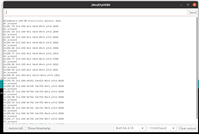
Example output:


