If you are familiar with prototyping Atmega328 based circuits on a breadboard, using the AVR-DB 28-pin through-hole package is very similar.
This is how I started with the process of familiarising myself with this chip before putting together the full emonTx v4 design. The very first step of course is to get an LED to flash! (The Arduino Blink example)
Through hole AVR-DB microcontrollers are available via standard distributors e.g Farnell: https://uk.farnell.com/microchip/avr128db28-i-sp/mcu-8bit-24mhz-spdip-28/dp/3594413?st=avr-db or from microchip direct (cheaper in bulk): https://www.microchipdirect.com/product/search/all/avr128db28
Blink
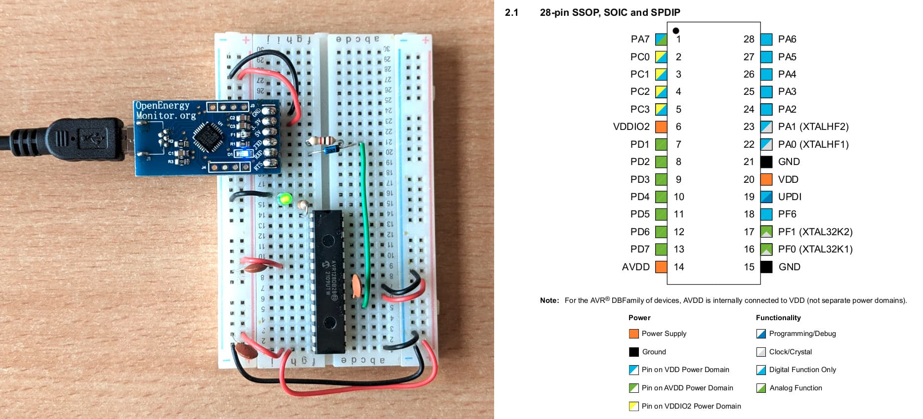
1. Breadboard layout
In the following breadboard circuit we are just routing power and ground to the relevant pins, the decoupling capacitors are there as suggested for best practice. The LED is connected to PA7 (pin 1) via a current limiting resistor and the programming of the AVR-DB chip is done using the UPDI programming interface.
Download the AVR-DB Datasheet here: https://www.microchip.com/en-us/products/microcontrollers-and-microprocessors/8-bit-mcus/avr-mcus/avr-db
UPDI is a single pin programming interface, Im using a simple resistor and diode to convert the USB to UART programmer into a UPDI programmer. Spence Konde has written a very useful guide on SerialUDPI here: AVR-Guidance/UPDI/jtag2updi.md at master · SpenceKonde/AVR-Guidance · GitHub.
Spence Konde’s documentation for the AVR-DB chip in general is top notch and he deserves every credit for making this chip accessible to those of us who like using the Arduino IDE.
2. Setting up the Arduino IDE
If you don’t already have the Arduino IDE it can be downloaded from https://www.arduino.cc/en/software
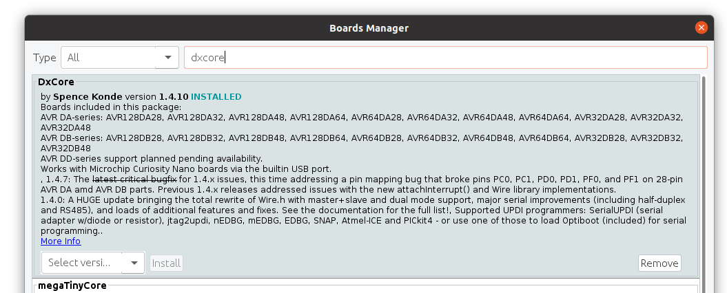
Once you have the IDE installed, you then need to install Spence Konde’s DxCore. This can be done by first pasting the following board manager URL in Arduino IDE > File > Preferences:
http://drazzy.com/package_drazzy.com_index.json
Then navigating to: Tools > Boards > Boards Manager, Select “DxCore by Spence Konde” and click Install.
3. The blink program:
The following basic blink program is all that you need to get blink working:
void setup() {
  pinMode(PIN_PA7, OUTPUT);
}

void loop() {
  digitalWrite(PIN_PA7, HIGH);
  delay(100);
  digitalWrite(PIN_PA7, LOW);
  delay(100);
}
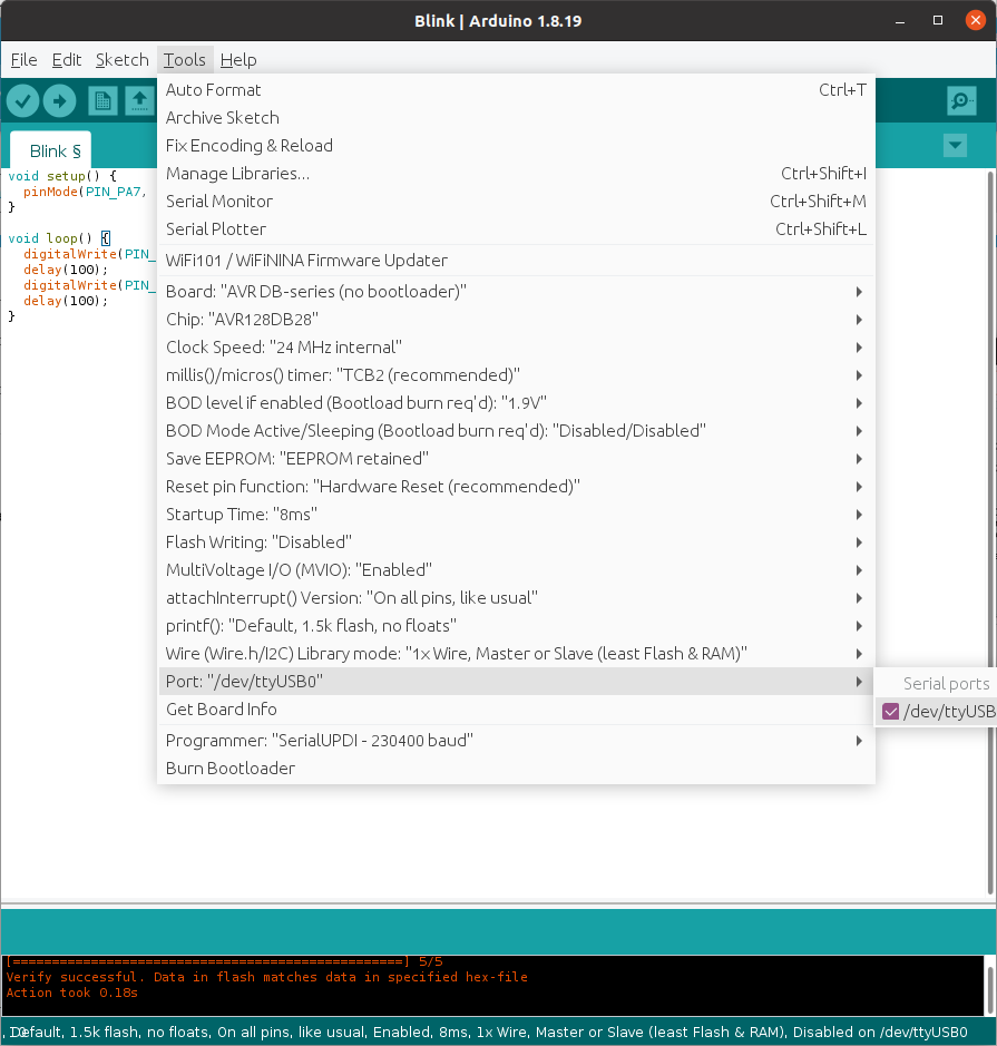
4. Upload settings:
There are quite a few compilation and upload settings that can be set with this chip.
- If you are uploading using SerialUDPI you need to select a (no bootloader) option.
- Make sure to select the right chip variant that you are using e.g AVR128DB28 in this instance.
- Im using the internal clock for this example so have the “24 Mhz Internal” clock option selected.
- The rest are all default settings but are detailed in a lot of depth in Spence Konde’s documentation for those interested in delving into these further.
5. Upload result:
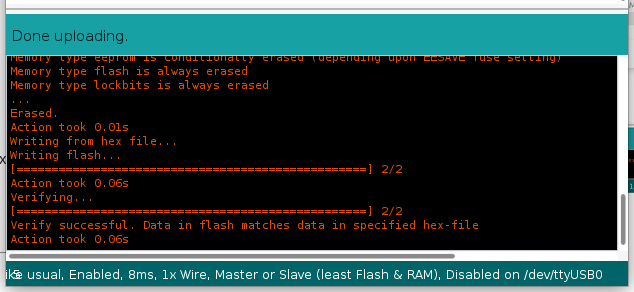
That’s it! Your LED should be flashing away! Hopefully that gives a quick overview of what it’s like using these chips, most of what you are familiar with from Arduino (ATmega’s) is transferable.
Not all libraries are supported yet as there are some low level code differences, the AVR-DB range has many similarities to the low level code used by the ATMega4809, which is used in the official Arduino Nano Every in terms of things like low level ADC code etc. The work required to get things running such as the continuous sampling code used by the emonLibCM library is however relatively straightforward and I will post the details of this for those interested in a follow up post.


