My emonTx is in the garage and I want to use the DS18B20 input to measure the temperature of the hot water tank upstairs.
The DS18B20 is " Fully compatiable and uses same pin-out as Sheep Walker Electronics sensors, modules RJ45 breakout boards and exstenders." according the shop description.
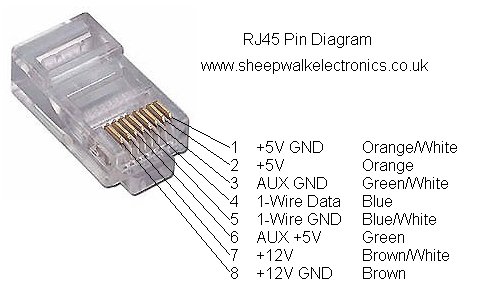
Sheepwalker “use RJ45 sockets wired to a standard layout that allows you to use cheap and readily available Cat5 Ethernet cables”
Their RJ45 pinout looks to be standard T-568B
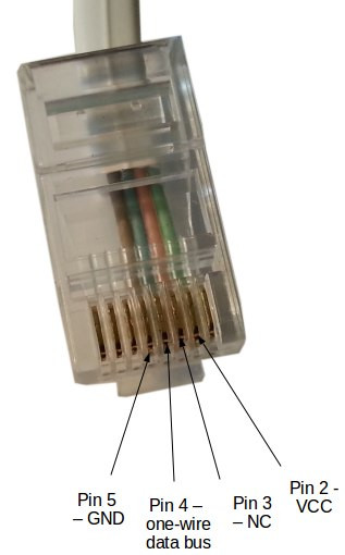
The pin out of the RJ45 Encapsulated DS18B20 temperature sensor is shown on
So I’ve run about 15m of cat5 cable and wired plugs to T-568B. The cable has tested out OK using an ethernet cable tester.
I used my own RJ45 extender to link the emonTX via the extension cable to the remote DS18B20.
The problem is I don’t get any T0 readout from the emonTx with the extension cable in the circuit so I’m clearly misunderstanding something and doing something wrong.
Reading are restored with the DS18B20 connected directly to the emonTX.
Hopefully someone can point out where I’ve gone awry!
Firstly, it’s not an Ethernet connection, it’s One-wire. So you must not swap the pairs around - both ends need to be wired Pin 1 - Pin 1, Pin 2 - Pin2, etc.
It’s the only device on the bus.
I’ll rewire as you suggest.
The sensor is 4 wires (4 colours) , pins 2-5 and initially I wired the cat5/RJ45 straight through using the same colours & pinout. This didn’t work and I assumed it was a capacitance/interference issue due to not using twisted pairs. Hence I regrouped, read the links I posted above and pinned out accordingly.
So I’m inclined to think it’s a simple wiring error. It seems right to keep the data and GND inside one twisted pair, and VCC can be part of another pair.
But only those 3 are used!
Also check that the Pin 1 - Pin 1 etc follows all the way through whatever adapters and couplers you have.
I think that depends a lot on the master’s interface design. You might struggle with 15m and only a 4K7 pull-up. But before considering making the pull-up stronger you need to determine if it’s pulling to 3.3V or 5V (there’s a thread about that here). My conclusion further down in that thread was that it’s that 4K7 pull-up that’s protecting the 3.3V input from too much current from the 5V source.
I went back to the start and belled the connections through the extender block and connected the Cat5 pin1-pin1, etc (so not as suggested in the links I originally posted). Used twisted pairs this time (unlike my first attempt where I’d continued with the colours of the DS18B20 cable pin out).
Anyway now got a solid sensible reading for HW tank without having to recourse to pull-up.
I’m a little suspicious of that cable. It appears to be a telephone cable that’s been used (certainly it uses the standard colours for a 4-wire telephone cable: blue - orange - green - brown) and I think it’s got stranded conductors, which raises two questions: first: are the cable overall dimensions correct for the RJ45 that’s been used, and second: has the RJ45 got the correct insulation piercing tang for stranded conductors?
I question the first because I don’t think the cable clamp is doing its job, and the second because there are two sorts - one for solid conductors and one for stranded, and if the wrong one is used, it won’t be reliable. Done properly, IDC connections are good. Done wrongly, they’re very bad, and there’s no middle ground.
No, its def. proper Cat5e cable - 4 pairs twisted solid conductors - left over from years ago when I put wired ethernet in the house first time around years ago.
Originally I thought I’d help myself by snipping off the striped conductors and follow through the 4 colours of the temp probe. Should have read up about one-wire before I started!
You were right, probably was originally a wiring error/not using pin1-pin1, etc, and certainly not helped by not using twisted pairs.
Thanks again for taking the trouble to have a look and comment.
You misunderstood me - I was referring to the cable and connector that is attached to the sensor, not the one you used. If you get trouble on that sensor in the future, that’s where I’d look first. I had to re-crimp one I have, and hot glue the cable in place as the strain relief was ineffective.
I raised that point because many Ethernet devices can auto-detect whether the transmit and receive pairs are swapped, i.e. a Type A to Type B, but 1-wire isn’t like that!
I suspect we’ll never know the true cause of the problem.
Sorry for being a bit dim there! Yes, I’d read somewhere that these probes can be a bit flaky, but then what do you expect for £8, I suppose. Good point about the cable being the place to look in case of future issues. That said, its now taped to the pipes and so should not now move…famous last words.