ESP gets garbled data from EmonTx shield

Hello. First a little background: I 2015 I got an EmonTx shield with an RF module and another RF module for a raspberry Pi. At that time it worked fine. But things evolved. I changed the RPi (which was also running Domoticz) for a NUC (and switched to Home Assistant). This rendered my Emon stuff useless. So at one time I had learned a bit about MQTT and got myself an Arduino Uno Wifi Rev2. I managed to get things working and got the measurements into Home Assistant. Until I noticed that the measurements were actually way off. The lowlevel A/D stuff was just too different on this device and I failed to properly convert it. Then I read about the EMONESP and decided to give that a try. I changed back to the original Arduino Uno.

I ordered the pre-programmed Huzzah, but (thanks to Brexit) it takes forever to arrive. I found I had another Huzzah around and tried to program that one. This wasn’t easy either. Which firmware to use? WifiRelay? Sonoff? firmware.bin? spiffs.bin? And how, without linux or python? I ended up installing Platformio and succesfully built it and uploaded it to the Huzzah. It appears to work fine.

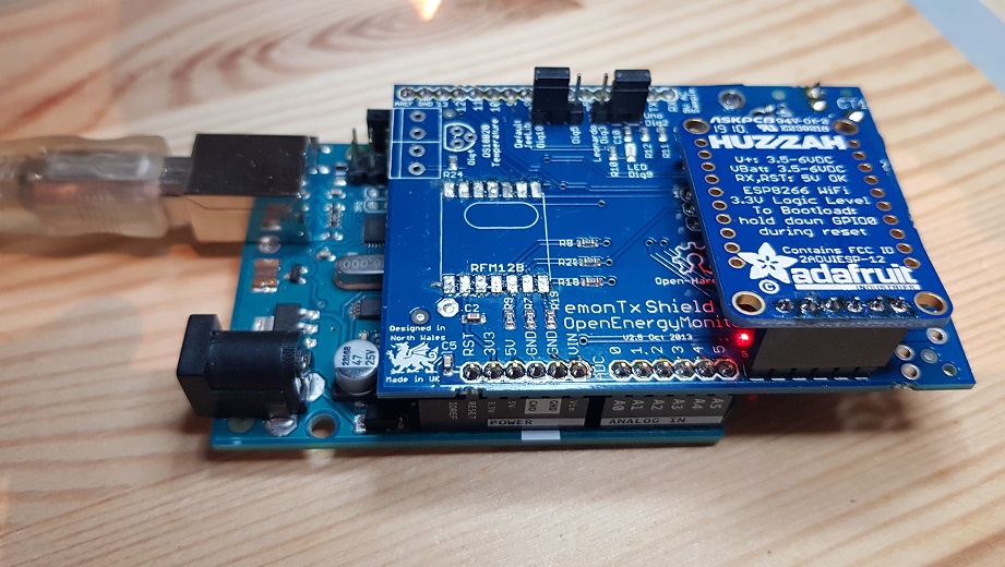
But the problem is that the Huzzah gets garbled data from the EmonTx Shield.

I based the Arduino software on this one. I found out I had to change the format of the serial data. I now outputs stuff like this:

13:56:48.772 -> ct1:530,ct2:1091,ct3:0,vrms:0
13:56:58.787 -> ct1:1109,ct2:1138,ct3:0,vrms:0
13:57:08.797 -> ct1:1246,ct2:839,ct3:0,vrms:0
13:57:18.811 -> ct1:1480,ct2:1201,ct3:0,vrms:0
13:57:28.805 -> ct1:1186,ct2:1404,ct3:0,vrms:0

And I switched from 9600 to 115200 baud.

On the Esp website it shows like this:

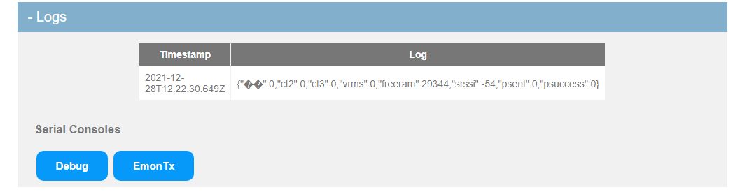
It also isn’t regurally updated. While the Arduino sends out data every 10 seconds.
I suspected that the RF module might interfere, so I desoldered that. But that didn’t help.
Also for the time being, I took out as much as possible from the Loop routine, so it’s now basically just sending out a string with random values and a 10 sec delay.

The EmonTx serial console looks like this:

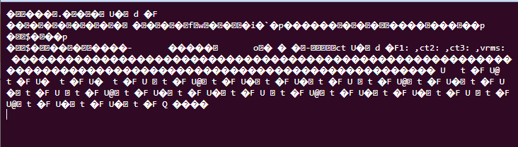
Lots of garbage with some readable text.

Welcome, Hans, to the OEM forum.

There can be two reasons for that:

  1. The baud rates do not match,
  2. The data being sent from the emonTx Shield is not in the format that the ESP8266 expects.

The data format looks to be correct for our software running in the esp8266, however unless you have our software in your ESP8266, I cannot be certain that it will be in the correct format.

If you are using the 3-phase PLL sketch, the latest version to use is here: Update to 3-Phase PLL sketch - #22 by Robert.Wall
All you need to do to disable the radio is not define “RFM69CW”, and define “EMONESP” instead. That will switch the the output to the correct format.

You must read the documentation that comes with the sketch for all the other settings, calibration and installation instructions.

The sketch (I presume you will need the 3-phase sketch where you live) needs to send no faster than 9600 baud because at anything faster, the PLL loses lock. You must change the baud rate in the ESP8266 sketch to match. From the documentation: "change Line 41 or thereabouts in the ESP8266 file “src.ino”.

I believe the ESP8266 compatible software is here: GitHub - openenergymonitor/EmonESP: ESP8266 WIFI serial to emoncms link

I cannot help you with platformio - when I tried it, it moved files and broke my system, it took half a day to put everything back to how it should be.
I use the Arduino IDE - all the installation instructions for the IDE and the libraries are in the “Learn” section here.

Thanks.
I’ve changed the baudrate to 9600 in both the Arduino sketch (i now use the one you recommended) and the esp sourcecode. In the latter I found it in debug.cpp.

Now I see nothing at all. Not even garbage.

When reading the docs I found something else. In this document they mention switching rx and tx signals on the 6-pin connector. This is something I didn’t expect. Is this also true for the Emontx Shield or only for the emonTx V3?

Edit:
Wow, yes! I quickly made a temporary connection like in the picture and now the data clearly appears in emonesp like it should.

Yes, I’m sorry - I should have mentioned it. I’ve no idea why it was done the way it was, but ALL OEM serial ports have the cross-over on the board, so the wires don’t cross externally. Tx is therefore looking for transmitted data coming in from somewhere, and Rx is looking for something to receive data it is sending out.

(If you look at the circuit diagrams, you’ll see: Rx on the processor connects to Tx on the header pins for the programmer, and Tx on the processor connects to Rx on the header.)

I guess it’s somewhat like the old male and female DB9 connectors. That often caused confusion too.

But for me it’s now time for the next step: getting correct measurements.
I notice that there are now several sketches around. For example the one I used at first, the PLL sketch you mentioned here. And I came across a ‘Continious Monitoring’ sketch which in which I also saw your name. This one has also watt/hour measurements, so that one is appealing. Which one do you recommend?
I only have 1 phase at home. I’m using 2 clamps: one for full and one for partial measurements.
(I have no problem tweaking the code to my own needs)

As you are in the Netherlands and mentioned the three-phase sketch, I assumed you needed it! If you have only a single phase, then the 3-phase sketch isn’t for you (though you can use it if you wish, but you must set the second c.t. to be on phase 1). If you particularly want the energy use accumulated in the Arduino, then I would recommend the new single-phase sketch for the emonTx Shield.

As you are not using the radio to reach your emonPi, the latest version for the emonTx Shield is actually the one here:
EmonTxShieldCM_rfm69n.zip (69.0 KB)

All you need to do is set the radio off (in EEPROM) and it should work for you. You can revert to 115200 baud in the ESP8266 if you wish (otherwise, change the sketch to 9600).
(Note: If you later want to use this sending the data by ISM band radio to the emonPi, it won’t work. This sketch uses the “native RFM69” radio protocol, not the “classic” protocol that the emonPi and the standard sketches still use. Wi-Fi is fine. See The emonPiCM for a full explanation.)

1 Like