EmonTx4 3-phase support with emonLibDB

Thanks to @Robert.Wall’s hard work on emonLibDB, the EmonTx4 now supports 3 phase electricity monitoring :tada: I know quite a few people have been asking for this!

emonLibDB is an electricity monitoring library for the EmonTx4 that is able to monitor continuously 3 voltage channels and 12 current/power/energy channels, three pulse inputs (or two pulse inputs and one low voltage analogue input).

Im going to cover in this thread:

  1. How to configure, upload and use the EmonTx4DB_rf firmware example that is included with the library. This example is the most versatile firmware example that is currently available using this library, but it does require changing hard coded configuration in the firmware source code itself and firmware compilation and upload using the Arduino IDE.

  2. How to upload a variant of the original EmonTx4 firmware that uses emonLibDB called EmonTxV4_DB_3phase_6CT. This firmware includes serial configuration and energy values saved to EEPROM but is limited to a fixed 3 phase 6 CT sensor configuration, with CT 1 & 4 on phase 1, CT 2 & 5 on phase 2 and CT 3 & 6 on phase 3.

Note: Neither example supports temperature sensing, emonLibDB does not support temperature sensing. Temperature sensing with the EmonTx4 is only available using the single phase emonLibCM library, see EmonTx4 DS18B20 Temperature sensing & firmware release 1.5.7 for more details.

It is also worthwhile consulting the emonLibDB user guide if you are trying to understand how to use and modify the firmware examples below, please see the PDF here: emonLibDB/emonLibDB User Doc.pdf at main · openenergymonitor/emonLibDB · GitHub or PDF converted to markdown here: https://github.com/openenergymonitor/emonLibDB/blob/main/guide.md

1 Like

How to configure, upload and use the EmonTx4DB_rf firmware example that is included with the library.

  1. Start by following the existing EmonTx4 How to compile and upload firmware guide. While the EmonTx4DB_rf firmware example does not use all of the libraries listed (it just needs emonLibDB and RFM69_LPL), it is worthwhile installing them all so that you have the capability to compile all EmonTx4 firmwares. I’ve updated the guide to include the new emonLibDB library alongside the others.

  2. Using the Arduino IDE, open the EmonTx4DB_rf firmware example. Navigate to:

    File > Examples > emonLibDB > Examples > EmonTx4DB_rf
    
  3. With the example open, save as a new local copy e.g EmonTx4DB_rf_mycopy.

  4. This example supports up to 12 CT sensors using the 6 CT EmonTx4 expansion board. I will be adding this to the shop soon, in the mean-time if you have a standard EmonTx4 with 6 CT inputs these additional inputs should be disabled by commenting out the line (line 33):

    #define EXPANSION_BOARD
    

    commented out:

    // #define EXPANSION_BOARD
    

    With EXPANSION_BOARD disabled, ignore the txPacket2 code in the example, this is for transmitting the data from the second set of CT sensors on the expansion board.

  5. Note that the Node ID for txPacket1 is set to 28 (line 42). If you have multiple EmonTx4 units, make sure that the NodeID set here is unique on your system. Set as required:

    uint16_t NodeID1 = 28;
    
  6. Configure the emonVs voltage sensor calibration values (lines 119-124). If you want to have 3 phase voltage sensing, make sure all 3 lines are present as default:

    EmonLibDB_set_vInput(1, 100.0, 0.16);  
     
    /* Include the next two lines if you have a 3-phase emonVS */
    
    EmonLibDB_set_vInput(2, 100.0, 0.16); 
    EmonLibDB_set_vInput(3, 100.0, 0.16); 
    

    100.0 here refers to 100% of the default calibration value.
    To be updated with more detailed note here.
    Please see emonLibDB user guide for more info as well

    0.16 refers to the voltage sensor phase calibration.

  7. Configure the CT channel calibration values (lines 126-131):

     EmonLibDB_set_cInput(1, 100.0, 0.3);         // 0.3° @ 20 A for 100 A CT
     EmonLibDB_set_cInput(2, 100.0, 0.3);
     EmonLibDB_set_cInput(3, 100.0, 0.3);
     EmonLibDB_set_cInput(4, 100.0, 0.3);
     EmonLibDB_set_cInput(5, 100.0, 0.3);
     EmonLibDB_set_cInput(6, 100.0, 0.3);
    

    100.0 here refers to 100A CT sensors. If you have 20A or 50A CT sensors change the relevant channels to 20.0 or 50.0 to match the CT sensor.

    0.3 refers to the CT sensor phase calibration.
    To be updated with more detailed note here.

  8. Link voltage and current sensors to define the power & energy measurements (lines 156-161). I’ve changed the defaults in this example below so that CT 1 & 2 is associated with V1 (phase 1), CT 3 & 4 is associated with V2 (phase 2) & CT 5 & 6 is associated with V3 (phase 3):

    EmonLibDB_set_pInput(1, 1);                  // CT1, V1 (etc)
    EmonLibDB_set_pInput(2, 1);
    EmonLibDB_set_pInput(3, 2);
    EmonLibDB_set_pInput(4, 2);  
    EmonLibDB_set_pInput(5, 3);
    EmonLibDB_set_pInput(6, 3);
    

    These can be adjusted as required. You could have CT 1, 2 & 3 on phase 1,2,3 and CT’s 4,5 & 6 all on phase 1. This would look like this:

    EmonLibDB_set_pInput(1, 1);
    EmonLibDB_set_pInput(2, 2);
    EmonLibDB_set_pInput(3, 3);
    EmonLibDB_set_pInput(4, 1);  
    EmonLibDB_set_pInput(5, 1);
    EmonLibDB_set_pInput(6, 1);
    

    Note: It is also possible to measure Line-Line loads, see Line-Line loads: example lines 175-188.

  9. Compile and upload your configured firmware to the EmonTx4. Note compilation and upload settings as covered in the EmonTx4 How to compile and upload firmware guide.

  10. To receive the radio packet data on an emonPi or emonBase first make sure that you are running LowPowerLabs radio firmware on the emonPi or emonBase receiver.

    If you have existing nodes running the original JeeLib classic radio format, the firmware on these will also need to be updated if everything is to continue talking to each other.

    If you have an emonPi make sure that it’s running the latest emonPi LowPowerLabs firmware, this can be uploaded from the local emoncms Admin > Update page:

    If you bought an emonBase alongside an emonTx4 and selected the standard radio format option the radio configuration should already be correct and ready to receive data from the EmonTx4 running the above firmware example.

  11. Configure emonHub to decode the EmonTx4DB_rf radio packet.

    If you have the latest version of emonhub with autoconf enabled, it will automatically populate the node decoder configuration below. If you have an older system with autoconf disabled, follow the following manual steps:

    On your local emonPi/emonBase navigate to Setup > Emonhub > Edit Config.

    If you already have a node configuration in the [nodes] section for the EmonTx4 under the same nodeid as above, remove this first.

    Add the following node decoder in its place (Adjust the nodeid to match the configured nodeid as set in the firmware above):

    [[28]]
        nodename = emonTx4_28
        [[[rx]]]
            names = MSG, Vrms1, Vrms2, Vrms3, P1, P2, P3, P4, P5, P6, E1, E2, E3, E4, E5, E6, pulse, Analog
            datacodes = L, h, h, h, h, h, h, h, h, h, l, l, l, l, l, l, L, H
            scales = 1.0, 0.01, 0.01, 0.01, 1.0, 1.0, 1.0, 1.0, 1.0, 1.0, 1.0, 1.0, 1.0, 1.0, 1.0, 1.0, 1.0, 1.0
            units = n, V, V, V, W, W, W, W, W, W, Wh, Wh, Wh, Wh, Wh, Wh, p, n
    
  12. That should be it! you should now see the EmonTx4 data appear both in the EmonHub log window and as inputs on the Emoncms inputs page :tada:

How to upload a variant of the original EmonTx4 firmware that uses emonLibDB called EmonTxV4_DB_3phase_6CT.

  1. Run a full update on your emonPi/emonBase from the local emoncms Admin > Update page. This will download the latest pre-compiled firmware options and associated emonhub node decoders.

  2. After finishing the update, connect your EmonTx4 to the emonPi/emonbase with a USB-C cable, refresh the page and check that port ttyUSB0 is listed in the update firmware section.

    Select Hardware: emonTx4, Radio format: RFM69 LowPowerLabs and Firmware: emonTx v4 3-phase, 6 channel firmware, lowpowerlabs v2.0.1:

    Click Update Firmware to upload the firmware.

  3. If you have autoconf = 1 enabled at the top of the emonhub config, emonhub should pull in the correct node configuration automatically.

  4. You should now see emonTx4_3phase_27 activity appear in the emonhub log:

    and inputs on the Emoncms inputs page:

  5. Serial configuration (requires latest version of emoncms core, should have downloaded as part of the update in step 1).

    Connect the emonTx4 to the emonPi/emonBase via USB-C again.

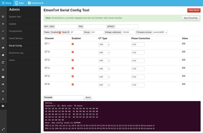
    Navigate to Admin > Serial Config.

    Stop EmonHub and Start Serial (Select port ttyUSB0 and baud rate 115200).

    After a couple of seconds the configuration interface should populate automatically with the existing or default configuration. Check that the configuration selected the correct Firmware version, it should be emonLibDB.

    Adjust the calibration values as required and then click Save to persist the settings.

I have updated the default nodeid’s for the example firmware’s above so that they are unique / less likely to be the same as existing emonhub node configurations. This also helps to ensure that the new emonhub autoconf feature works correctly.

The updated and suggested nodeid’s are:

  • 27: EmonTxV4_DB_3phase_6CT
  • 28: EmonTx4DB_rf (packet 1)
  • 29: EmonTx4DB_rf (packet 2)

I have also fixed the emoncms serial configuration user interface to support the emonLibDB calibration format.

For further documentation on 3 phase measurement using the EmonTx4 please see the docs here:

https://docs.openenergymonitor.org/electricity-monitoring/ac-power-theory/3-phase-power.html#measuring-3-phase-power-with-an-emontx4-and-emonvs

and for use in North America:

https://docs.openenergymonitor.org/electricity-monitoring/ac-power-theory/use-in-north-america.html#part-2-using-an-emontx4-and-emonvs

thanks again to @Robert.Wall for his work updating these!

Yes, great Trystan,
I will implement it tomorrow.
2 questions:

1: Any plan to create a binary with 12CT sensors ?
2: Any plan to be able to decide which CT is connected to which phase, sometime you need 3 CT on phase 1, 2 on phase 2 and only 1 on phase 3 ?

Based on

and the answer to part 2, wouldn’t this come to 312 = 531441 separate sketches to cover all possibilities?

The library (emonLibDB) is capable of any pairings of current and voltage. If you download the library from this forum, and look at the documentation, you’ll see how it’s done. This was the extent of my involvement.

Hello,
Thanks for the input.

For my second question, I was more in the project that a drop down list (like the power of the CT) can be added to the Serial Config page to allow tho chose which CT go to which phase.

I don’t like to have to do a compilation of a library, with all the other software I need.

So it’s installed, And I will have to create my feed, recreate my dashboard, and see how it’s going.
At least now I have the 3 phases, positive power on all 6 CT, so I’m gona say so far so good!
Good work

I think that’s something we are going to look at for a future version of the firmware. The focus to this point has been on the core functionality of the emonLibDB library and providing the capability for those happy to compile and upload to configure the emonTx4 in any way they would like. It’s been a ton of work by @Robert.Wall to get to this point :slight_smile:

Great to hear!

Once I have the 6CT Extender in the shop, I’d be happy to put together a couple of binaries with set configurations e.g:

  • Single phase, 12 CT
  • 3 phase, with phases allocated to CT channels e.g in the following pattern: 1,1,2,2,3,3,1,1,2,2,3,3

I will keep an eye on how the requirements and discussion around this evolves and consult and work with @Robert.Wall as he sees fit :slight_smile:

After discussion with @glyn.hudson about most convenient phase allocation for the standard EmonTxV4_DB_3phase_6CT firmware example. We have decided to change it to:

  • CT1 phase 1
  • CT2 phase 2
  • CT3 phase 3
  • CT4 phase 1
  • CT5 phase 2
  • CT6 phase 3

In short 1,2,3, 1,2,3 rather than 1,1,2,2,3,3.

The latest version available via the Emoncms RaspberryPi upload mechanism is now 2.0.2 with this configuration.

Hmm,
Is it possible to have the release note, so I can decide if I upgrade, and change my whole config again!
But now are you going to keep it that way ?

This seems a bit more logical to me. Principally, when the extender board is present, the progression will continue: 1,2,3, 1,2,3, 1,2,3, 1,2,3.

@TrystanLea
You’ll probably be expected to produce a .hex file (or several) for split-phase systems too.

I’d point out to everybody that emonLibDB is completely uncommitted as far as the allocation of phases is concerned. It obeys the set-up instructions, and those come from the sketch via its API.

1 Like

2 posts were split to a new topic: Successful New TX4 Install

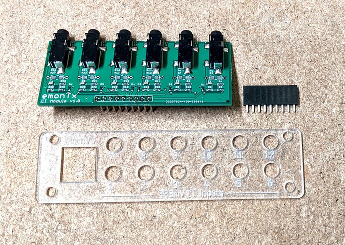
The 6 CT Expansion board is now available in the shop
EmonTx4 6 CT Expansion board - Shop | OpenEnergyMonitor

and the installation and firmware guide can be found in the docs here:
6 CT Expansion board — OpenEnergyMonitor 0.0.1 documentation

The expansion board is currently listed in the development boards section of the shop as it’s really for those comfortable with soldering the header and manually configuring, compiling and uploading the firmware using the Arduino IDE. We can do these steps for you if required when ordering the expansion board alongside an EmonTx4 in the same order, please email us first at [email protected] to discuss how you would like us to configure the unit.

1 Like