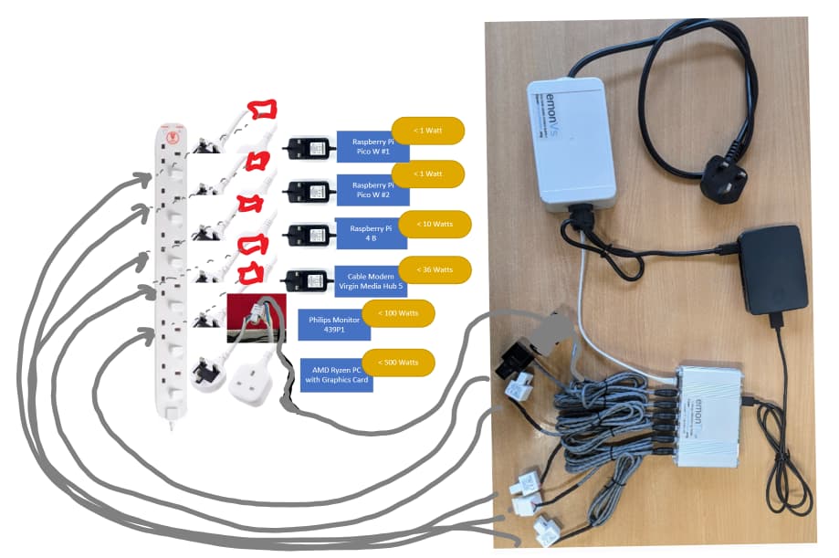
Are the CT sensors accurate enough to measure low power individual components of my home lab?
Raspberry Pi Pico (<1W)
Raspberry Pi 4B (<5 W)
Cable Modem (rated 36W)
…while simultaneously measuring more power hungry components?
Gaming PC with graphics card (around 400W)
My application is different than most I’ve seen on the forum and in the documentation. I want to see the usage of individual components instead of full circuits.
The ‘current’ input to the emonTx4 is in fact a voltage - 0.333 mV rms maximum (sine wave). You can use any current transformer with a 0.333 V output, all you need to do is adjust the calibration.
So if you find a c.t. with a rated current of (say) 1 A, then your cable modem will show 15% of maximum power (well within its capabilities), whilst your Pi Pico will show about 4%. The latter is marginal and there certainly won’t be a lot of accuracy in the reading.
However, this is ignoring power factor so the currents are likely to be significantly higher than the values for a load with a unity p.f, so the current measurement will be easier, but you’ll need to pay more attention to getting the phase errors compensated accurately. Plus of course at those powers, the losses in the power supplies stand to be significant.
You can of course multiply the primary turns of the c.t., which has been mentioned here very many times, and which will increase the sensitivity by the same factor as the number of passes through the c.t. (so your 1 A c.t. could be a 5 A rated one with a 5 At (ampere turns) primary winding of 5 turns carrying 1 amp).
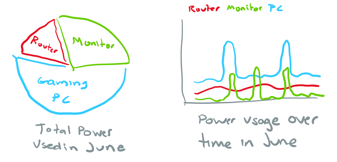
Just to be clear on the focus of this thread: My questions center around how to accurately capture the underlying source data, i.e., the detailed power consumption of individual components.
Aggregating and visualizing is a topic for another day.
OEM seems like a vibrant community! I look forward to contributing by doing a write-up of the whole project once done
The ‘current’ input to the emonTx4 is in fact a voltage - 0.333 mV rms maximum (sine wave). You can use any current transformer with a 0.333 V output
Understood.
So if you find a c.t. with a rated current of (say) 1 A, then your cable modem will show 15% of maximum power (well within its capabilities), whilst your Pi Pico will show about 4%. The latter is marginal and there certainly won’t be a lot of accuracy in the reading.
At what percentage of maximum current do CTs tend to lose accuracy? Based on this paragraph, I am inferring that 15% of maximum current should be accurate, while 4% is low enough to become inaccurate.
you’ll need to pay more attention to getting the phase errors compensated accurately
Okay, I’ll do a bit of searching on how I would accurately compensate for phase errors.
the losses in the power supplies stand to be significant.
Yes; One of the big reasons I am interested in capturing power on the AC side is to measure the effect of higher efficiency AC to DC power adapters on system power draw.
You can of course multiply the primary turns of the c.t., which has been mentioned here very many times
Conceptually makes sense, and I will look for other examples of that on the forum.
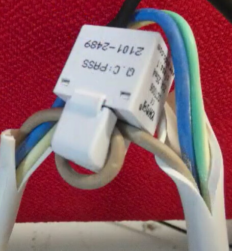
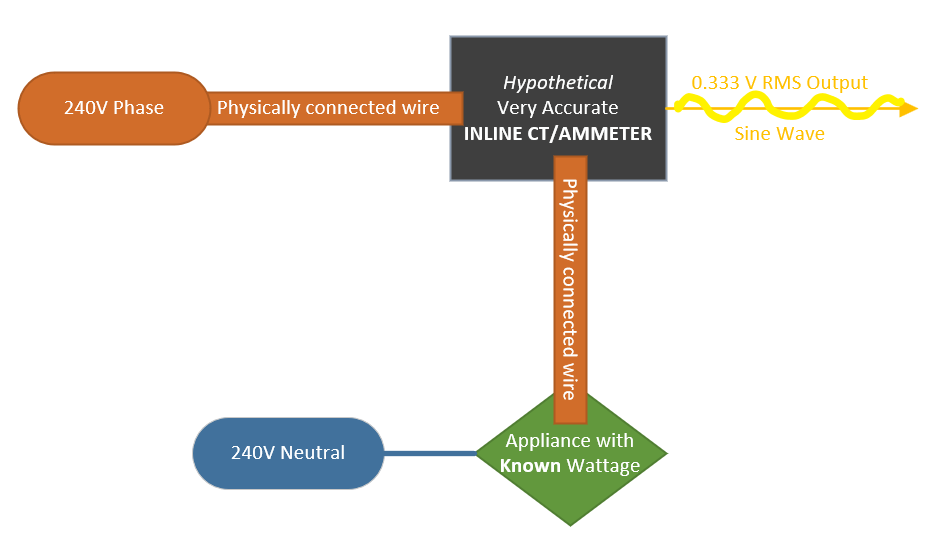
Final thought: since you say I can use “any current transformer with a 0.333 V output”, that makes me wonder if inline devices might exist that would be more accurate than clamp CTs because the copper wire is physically connected to them.
Does something like this exist? If so, would the 0.333 V signal to the emonTx4 still carry all the information required for the Arduino Maths to calculate real power?
How much are you prepared to pay for your c.t? This is very roughly the same question! You get what you pay for. A single ‘revenue’ grade c.t. could well be comparable with the complete emonTx4 in terms of cost.
And that galvanic connection brings serious isolation and safety problems with it. It’s something we strongly advise against.
At the current levels you want to measure, you can use wire thin enough to make wrapping quite a few turns through the CT’s wire window fairly easy. (the WW on the CCS CTs is ~19mm x 19mm) I wrapped 60 turns of AWG 24 solid core wire on a Magnelab SCT-0750 5 Amp CT and other than being a bit time consuming, it wasn’t difficult or too unwieldy. Total length of wire was about 6 feet.
23 turns should be fairly quick to do. 93 turns won’t be as quick, but with thin wire should still be doable.
I use 100 turns of enamelled copper (NOT at mains voltage - only 6.5 V) to test c.t’s up to 500 A.
I think the answer to that will be a firm NO.
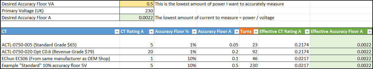
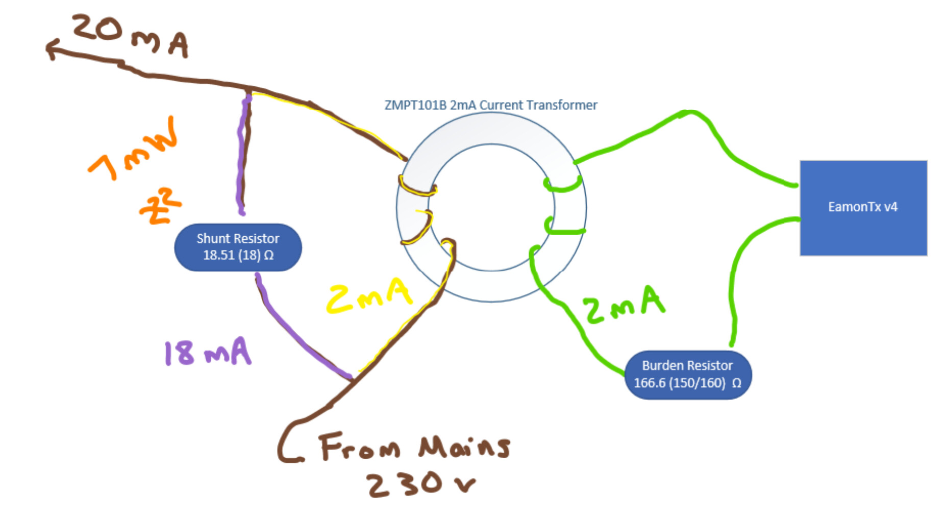
However, I can offer a suggestion - a 20 mA shunt (which you will have to make yourself, because I can’t envisage one of those being readily available either) and a ZMPT101B 2 mA c.t. (not the ZMPT101B module) to provide the necessary isolation. You will need to make the shunt resistance such that with the c.t. primary winding in parallel, the current shares in the ratio 18 mA in the shunt to 2 mA in the c.t. primary winding. You’ll then get 2 mA in the c.t. secondary winding which can have a burden to give the voltage you need for the ADC - in this case 333 mV for 2 mA = 166.6 Ω . The voltage across the shunt will also be 333 mV of course as the c.t. has equal turns on both windings.
With regards to the CCS option and the J-Hardware shunt option those are definitely still on the radar! I’d rather be clever with the use of cheaper options, but if throwing money at the problem becomes necessary, I’ll do it!
A “shunt” is simply a resistor that has a relatively low value (relative to the instrument - in this case the primary winding of the ZMPT101B - connected across it) so that the major proportion of the current passes through the shunt and the minor proportion flows through the instrument, the transformer. If you want 20 mA in total to flow, and of that 2 mA to flow through the transformer, then you need 18 mA through the shunt, and because both see the same voltage, the resistance of the shunt is 2/18 the resistance that the transformer winding appears to be, NOT the resistance you measure with a multimeter (because it’s a transformer, and its burden is reflected through the transformer and appears to be in the primary circuit as well as the resistance of the copper winding).
The ZMPT101B is a 1:1 transformer - 2mA primary current equals 2 mA secondary current. Equally, 333 mV secondary voltage equals 333 mV primary voltage. So ignoring the windings for a reasonably close approximation, using R = V/I, we get the value 166.6 Ω, exactly the value of the burden resistor you need. (Had the transformer not been 1:1, the resistor wouldn’t have been the same.)
Therefore, your shunt needs to have a resistance of 18.51 Ω. At 20 mA, this will dissipate only around 7 mW, so an ordinary 18 Ω, 0.2 W resistor will be fine. This will change the calibration - 20 mA will no longer be 100% (it is slightly less) and in any case, the nearest burden resistor you will buy is 160 Ω (or even 150 if you can’t get 160), so you then need to recalculate the current that you would need for 333 mV at the emonTx4 input, and this becomes the calibration factor to use in EmonLibDB_set_cInput( ... ); (You might like to pretend it’s amps rather then milliamps, because I’m not sure whether the numbers might get truncated in the processing or not.) You’ll probably need to adjust the calibration because of the winding resistance we ignored and tolerances on the resistor values (which is why I always rounded down).
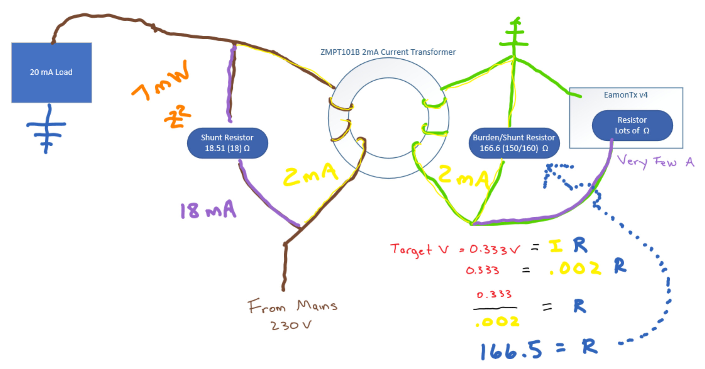
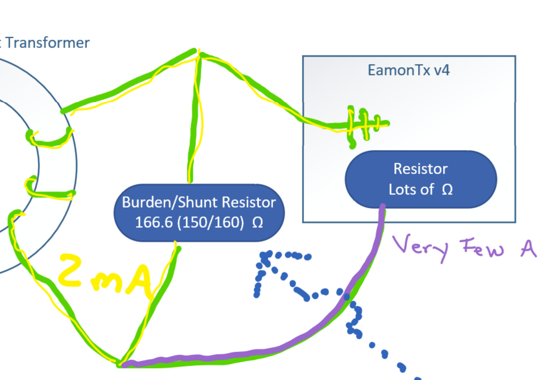
Not quite. The primary side is correct, but on the secondary side the burden should be in parallel with the transformer secondary winding, not in series with it.
The 2 mA secondary current flows in the burden resistor and develops the 0.333 V required by the emonTx4. As you have it, the current transformer would try to generate as high a voltage as it needs to make the current flow, but the emonTx input is a very high resistance, meaning very little current could flow so it’s likely you would damage or destroy the emonTx with excessive voltage, but for the protection we included. It certainly wouldn’t work as you intended.
Question: Does it matter whether I wire the ground of the secondary circuit like the above diagram (ground separately) only connect to ground side of EamonTx?
Yes it does. The sleeve of the 3-pole plug is earthed in the emonTx4, via the earth terminal in the emonVs. (But only an a.c. earth in its predecessors). Ideally, you don’t want a second (parallel) path to earth.
If you’re designing a p.c.b, remember to keep as much distance as possible between the mains side and the emonTx4 side so that there’s a long “creepage” path between the mains and the emonTx4.
You can look at the p.c.b. layout for the emonVs as a reference (there are milled slots there between the 3 lines, neutral and earth at the terminal block, to increase the creepage distance, but not beneath the ZMPT101Bs).
I would definitely not trust mains on a prototype plugboard, and if you use stripboard you’d need to totally remove the tracks between the mains side and the emonTx4 side.