emonTx V4, emonVS in North America

I’d like to start a thread regarding the use of the new AVR-DB, emonTx V4, emonVS, and burdened CTs in the US and North America. Currently the Use in North America guide seems to be geared toward emonTx V3, unburdened (current type) CTs, and a commercial AC-AC power adapter.

Here’s a possible recipe as a conversation-starter, looking at the current ordering form in the shop.

EMONVS POWER SUPPLY & AC SAMPLE

Order this with “No Plug: emonVS”. Add a US NEMA 5-15P cable such as the 189-411006-01-ND from Digi-Key.

CT1: None 200A 100A (default) 50A 20A

CT2: None 200A 100A 50A (default) 20A

Assume CT1 and CT2 would be used on the mains. We would need something with a larger opening than any of the options currently in the shop. My understanding is that one of the common standards in a US household, 200 amp service, will often use 4/0 AWG aluminum. That cable would be .46 inches (11.684 mm) in diameter (wiki). The EChun CTs in the shop are listed as having 6mm openings.
[See below - Moderator (RW)]

I know there have been various conversations about finding CTs for US mains in the past, and there’s a nice list of Magnelab, Wattcore, and Continental Control Systems options in the emonTx V3 documentation.

For the sake of discussion, I’m going to put forth the WATTCORE WC3-100-MV333 (datasheet) as a possibility (Amazon, MetersUSA).

Anything I missed? Thoughts? Feedback?

That’s not correct. I have a 100 A ‘Shop’ c.t. in my hand and the opening is 12.5 mm (½" in old money), but 12±0.3mm on Echun’s own data sheet. The 200 A one is listed on the Shop page as 19 mm and as 19.4±0.5mm on the data sheet.

You also need to bear in mind what @Bill.Thomson has written about the actual current demand of the US 200 A service: US 200 Amp Service explained or Do I need a 200 Amp CT?

Other than that, you are generally on the right lines. I’m not sure whether The Shop will offer a US version of the emonVs with only two voltage inputs, because you don’t need the third one. You’ll be pleased to note that the pesky “USA” calibration change will no longer be needed.

The “Use in N.America” page will be updated when time allows (even though it isn’t and never was specifically for the emonTx V3). All the c.t’s mentioned on this page will be suitable provided the 333 mV version (where available) is requested - in fact, any 333 mV output c.t. should be suitable, though you will probably need to determine the correct value to enter for the phase error, as it’s not realistic for us to evaluate or check every one available.

Cool! So the 200A CT in the shop is a candidate for use in North America!

My own experience bears this out. I have been using 100A Wattcore CTs with my emonTx since Robert, Bill and others helped me get going in 2015.

So which would be the better suggestion to someone just getting started? The 200A option in the OEM shop, which has an adequate opening, is easily ordered from the shop and has a known phase error; or a CT like the Wattcore I proposed, which Bill points out is more right-sized for most US homes, but is more difficult to source, and probably requires the user to determine and enter the correct value for the phase error?

Note:
I got confused about the size of the Echun CT opening because the words “Voltage O/P” in the center of the line for the 200A option on the shop page links to the 20A detail page. You have to click “200A” or “CT sensor” to get the 200A page. It’s a little funky right now.
Screen Shot 2023-04-08 at 3.17.47 PM

Not just the 200 A one - all of them! Too much Ctrl-C — Ctrl-V @Gwil - can you change this please? The link needs to be the whole line - like the 20 A one, and each to its own page, not all to the 20 A one!
This needs deleting from the bottom 3 of the list items:

</a><a href="https://shop.openenergymonitor.com/20a-split-core-current-transformer">

Yes. The insulation!

11.6mm is the conductor OD.

When the jacket is taken into account, the OD is in the range 14.96 to 15.88mm (.589 to .625 inches)

Thanks, @Bill.Thomson! In which case, the 200A CT is the only one in the OEM Shop that will work. I am interested in your opinion of this option, versus other options like the Wattcore 100A CTs, which are closer to the right burden for the current being measured, but perhaps less convenient to obtain and calibrate, especially for newer users.

I am assuming there is some loss of resolution when one measures with a 200A CT versus a 100A CT.

On the other hand, if the 100A CT isn’t calibrated correctly, with the correct phase angle, there is a loss of accuracy.

(I’m kind of hoping the answer is, “The 200A CTs in the OEM Shop will have plenty of resolution. Go with those!” Otherwise everyone in the US has several options to choose from, and it will be harder to establish a common standard for US users to collaborate with.)

Sorry about that. Just fixed all the links.

1 Like

On the back of this - is a “split phase” (or 2-input) emonVs anticipated for the N.American market? I guessed it would be when I wrote my response above.

I’ve asked Glyn, don’t think this is set in stone: he thinks the cost difference between fabricating three and two input boards will be minimal. Therefore, there will likely be a single and three input option. The firmware would need to be able to accommodate split-phase monitoring.

I think it will - it just needs proving.

It is interesting to contemplate how to deliver a signal to both inputs in my home, and I think most North American homes.

The only outlets I have in the house that are connected to both legs are the 240V outlets: the oven, the clothes drier, and an outlet in the garage for the OpenEVSE. None of these are at all close to the main service panel.

Next to the service panel I have some 120V outlets that I’ve been using for my two emonTx V3 AC/AC adapters.

If the emonVS had two inputs and two NEMA 5-15P cables supplying those inputs, I think I could monitor voltage on both legs. My existing outlets are either on opposite legs already, or I could have an electrician add an outlet or change the breaker of an existing outlet to achieve this. What I’m envisioning in this mode is that, inside the enclosure of the emonVS, the two “N” and “GND” wires would be pigtailed (Y-connected) to “N” and “E” terminals of the PCB, and the “HOT” wires would go to L1 and L2.

Another thought. The Neutral center leg in a US service panel is earth-grounded, right? Would it work to use a pair of NEMA 1-15P (two-prong) cables. One would go to L1 and E, the other to L2 and N.

A third option would be to have an electrician install a 240V outlet next to the service panel. This is my least favorite. I think an electrician would think this really odd. The cable involved would be really unfamiliar to most users. It would look like the emonVS was plugged into an EVSE outlet.

Can you absolutely rely on that, always?
If there was a fault and the neutral had become detached, the fault current to earth would flow via your flexible cables and the emonVs p.c.b. I suggest this is a very bad idea. The protective conductor is kept separate from the live conductors (and remember, the neutral is a live conductor) except for the one connection for very good reason.

A 4th option would be to have your 'trician wire your emonVs into a separate 3-pole fused switch - if you west-ponders have such things. We have 2-pole with one fuse for permanently wired appliances, for example:

I would consider it not safe to have two independent sockets - there is still a live supply inside the box when only one is unplugged - hence the need for a common 4-core cable and a 3-pole switch.

We have a thing called a “fused disconnect switch”. I think they are used to disconnect an air-conditioner for service. Like this: https://www.homedepot.com/p/GE-30-Amp-120-240-Volt-Fused-AC-Disconnect-TF30RCP/100576894

That is a very good point. I suspect there are codes that disallow two independent sockets for that reason.

Access Denied

You don’t have permission to access “http://www.homedepot.com/p/GE-30-Amp-120-240-Volt-Fused-AC-Disconnect-TF30RCP/100576894” on this server.

Reference #18.32051702.1681054974.188bd229

Probably a regional check by the site?

Here’s the device.

And the description.

The GE 30 Amp 120/240-Volt 240-Watt Fused (requires 2 fuses installed on the back side of the puller). AC Disconnect has a NEMA 3R-rated steel enclosure that is both rust- and corrosion resistant for outdoor use. This safety switch is intended to disconnect power from an air-conditioning unit and uses lug wire range AWG #14 - 3 copper/aluminum. This single-phase disconnect is ANSI certified and UL listed with a maximum load of 240-Volt.

  • Use to disconnect power from an air-conditioning unit
  • NEMA 3R-rated steel enclosure for outdoor use
  • Rust- and corrosion resistant
  • Fusible - requires 2 fuses that are installed on the back side of the puller
  • Single phase
  • Lug wire range is AWG #14 - 3 copper/aluminum
  • 120/240-Volt
  • 3 HP maximum
  • The fuse classes accepted are: H, K1, K5, K9, RK1 and RK5 up to 30 amps
  • ANSI certified and UL listed

At least some of that is going to depend on a “new” user’s knowledge of some basic electrical engineering.
For a “non-technical” user, the OEM-Shop-sold CT is likely the best way to go.

Correct.

Again, correct. Especially with devices that have a low power factor. i.e. the worse the power factor is,
the more the accuracy goes out the window.

Speaking of which…
333 mV output CTs with very low phase shift as well as good linearity over the range of 1 to 120% of their rating are available. The downside is they aren’t cheap.

If a user is technically inclined, then this is one hell of a deal:
https://www.ebay.com/itm/134410329423?_trkparms=amclksrc%3DITM%26aid%3D777008%26algo%3DPERSONAL.TOPIC%26ao%3D1%26asc%3D20221115143056%26meid%3Dfd64a8f793bf43daaf1617b439270f08%26pid%3D101612%26rk%3D1%26rkt%3D1%26itm%3D134410329423%26pmt%3D1%26noa%3D1%26pg%3D4375194%26algv%3DRecentlyViewedItemsV2%26brand%3DStahlin&_trksid=p4375194.c101612.m4236&_trkparms=parentrq%3A66d1df571870a12af280fb77fffd2b7e|pageci%3A79bb487e-d6f2-11ed-ba19-eab7b217ab98|iid%3A1|vlpname%3Avlp_homepage

It’s a revenue grade Wh meter with RG CTs and the cal certs for all three.
Not bad for 69 bucks. (49 for the pkg, 20 for shipping)
It’s a Modbus device, but emonCMS now has a Modbus interfacer. That should make using it fairly easy.

A definite no-no. Here’s one example of why:

Perhaps not. e.g. I have a wood lathe in my garage that happens to be about 3 feet from my load center. (circuit breaker panel) I use a VFD with a 3-phase motor to give me electronic speed control.
(no more mucking about with the belt to change speeds) The VFD is a 240 Volt device, hence I installed a 240 V outlet near the Load Center. Of course, this is an “oddball” example.

Robert makes a good point there.
An electrician friend who was the Electrical Superindendent of the town he lives in, (he retired about 6 years ago) told me they routinely found flaky neutral connections at the customer’s electrical service weatherhead about once a month. Sometimes a little more often, sometimes a little less, and sometimes more than one customer.

This is really helpful, and it makes me think the next step in this conversation is to suggest a path for a “new/non-technical user” and a path for a “experienced/technically-inclined user”.

The New/Non-Technical User

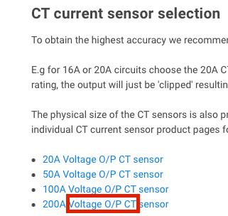
Makes sense. So the recommendation would be the two 200A CTs for the mains. The emonVS-PSU would be ordered without a power cable, and the user would order a NEMA cable from Digi-Key or get one from a local hardware store.

Would they need a grounded, NEMA 5-15P cable, or could they use a two-prong NEMA 1-15P cable? I ask because the emonTx V3 + AC/AC Adapter was an ungrounded, 2-prong setup. Was that actually OK? And then wouldn’t this be OK with emonTx V4 + emonVS-PSU?

The new/non-technical user would be in the mode of the statement that is currently in the “Use in North America” guide.

Fortunately, because the voltage balance between the two legs is good, little error is introduced by assuming the voltages are equal in magnitude.

That’s the mode we’re all in right now, with our AC/AC adapters, as far as I know, and we’ve been happy.

And the new/non-technical user would be getting less resolution than they could have had if they’d used 100A CTs, but being a new/non-technical user, they are likely better off because of the accuracy they get with CTs that are known and calibrated.

The Experienced/Technically-Inclined User
Let’s assume that this user is interested in the extra resolution available by using 100A CTs. This user might invest in the ACTL-0750 Split-Core CT - Continental Control Systems CTs Bill mentions.

Maybe they’d get the Wattnode Revenue Meter deal that Bill found, use two of the 100A CTs, and have a spare, third CT and Stahlin enclosure to do whatever with, and still have spent about half the cost of the ACTL-0750 CTs. (True?) Or maybe they’d use the Wattnode and learn about connecting the Modbus interfacer.

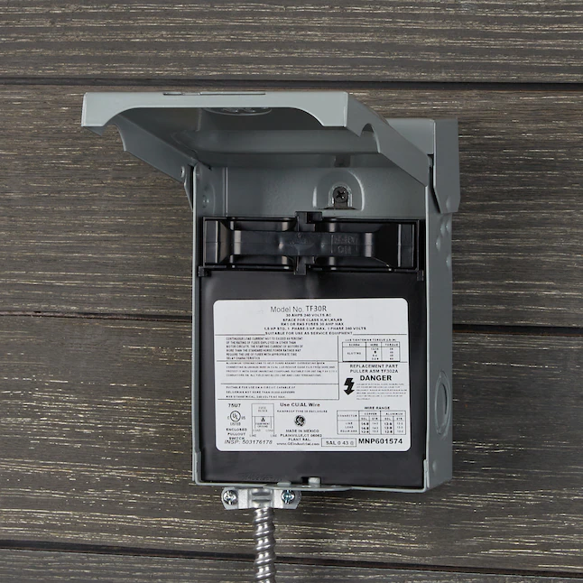
Next let’s assume the 2-phase firmware has become available for the emonVS-PSU. This technically-inclined user would connect their emonVS-PSU to monitor both mains legs in their service panel. To do so, the user would work with an electrician to install either an outlet or a hardwired appliance-style junction box connection.

If they use an outlet, do they need a ground connector? (Similar to the question above about the NEMA 1-15P or 5-15P.) If so, they’d need to use a style of plug and receptacle that split the ground and neutral conductors, such as NEMA 14-30. If not, they could use one that didn’t have a separate PE, such as NEMA 10-30, and leave the “E” terminal empty on the emonVS-PSU PCB.

Their other option would be running wires in conduit to a junction box with a disconnect switch, and in conduit from the junction box to the emonVS-PSU cable gland. Like an appliance, correct?

Question: would this user now need to indicate, for each emonTx V4 CT input, the corresponding circuit’s voltage connection? In other words, is the voltage of this circuit the difference between (a) L1 and L2 (b) L1 and N or (c) L2 and N? It seems like they would need to specify this in order to take advantage of the increased accuracy available by knowing each of these independently.

(At this point the experienced user is really hoping there is a significant improvement in accuracy from measuring both inbound legs in their service panel. Still, they are having a good time and they are learning a lot.)

I would use the term non-technical sans new.
A user might be new to OEM, yet have a tech or engineering background.

According to the NEC, a device with a metallic enclosure must be grounded.
In fact, all non-current-carrying metallic components of an electrical system are supposed to be grounded.

The AC/AC adapter you referred to is enclosed in a non-conducting housing, hence no requirement
for it to be grounded.

Yes. See answer above.

If the enclosures are metallic, they need to be grounded.

Although it’s a very nice package, I’d guess the actual number available is limited.

two phase?

Do you mean split-phase?

The North American split-phase system is a single phase split into two legs that are mirror images
of each other.

To meet code, the outlet must have a ground connection.

That would work.

If the “E” terminal is connected to the emonVS-PSU enclosure, the 10-30 connector won’t meet code.

That’s an option, but the ground requirement needs to be met here too.

I’m going to leave this one for @Robert.Wall. I know I’ll forget something and end up giving you
what amounts to a partial answer.

Thanks, Bill.

I still don’t understand why the emonTx V4 + emonVS-PSU would need a power cable with PE.

The emonTx V3 + AC/AC adapter is safe. This incredible organization and the community that surrounds it discussed, developed, vetted, scrutinized, tested, and used this setup for many years now. So as I ask my question, I am taking as axiomatic that the emonTx V3 + AC/AC adapter would have a PE connection if it needed one.

The emonTx V3 is a device with a metallic enclosure, right?

The emonVS-PSU is also enclosed in a non-conducting housing, right?

I can’t check my emonVs at present, I’m in the middle of testing the radio side of the emonTx4 & emonPi. However, there is an earth connection to the emonVs and I’m almost certain it’s carried through into the emonTx4, and it’s there for EMC compliance reasons.

I need to carefully read the relevant post, disentangle all the references to parochial standards and most likely do some tests I haven’t yet been able to do before I can answer what I think the question might be.