The NEC says that unless a device is double insulated, it must use a PE connection.
Indeed it is.
I should’ve qualified that statement though. The devices I was referring to are those that have mains wiring connected to components inside of said enclosure.
The NEC treats low voltage devices (there are several classes of LVDs) differently than mains
powered devices. The emonTx is a LV device, hence doesn normally pose the same danger of
electrical shock as a device that has a metallic enclosure and a power cable connected directly to the mains. (that’s not to say there aren’t any safety considerations with such a device)
That said, it’s never a bad idea to ensure all metallic enclosures are grounded. If nothing else, it can help mitigate EMI/RFI issues.
I don’t know for certain as I don’t have one. It looks as if that’s the case from what I can tell
going by the picture in the Shop section of the site.
Maybe the thing I am missing is that the emonVS-PSU and emonTx V4 were contemplated as one device for the purposes of determining EMC compliance, etc. Together they would comprise a mains-connected device, certainly.
From my perspective, I was thinking of the emonVS-PSU as the mains-connected device (similar to the AC/AC adapter) and the emonTx V4 as a low-voltage device (similar to the emonTx V3).
This statement is a fair way to settle the matter from my perspective.
Thanks. I can restate the question as well, because I’m not sure how clearly I stated it the first time around.
Assuming there is a future configuration of, and firmware for, the emonVS-PSU available for monitoring both legs of US split-phase power, I am curious if the user will need to specify, for each input they monitor with the emonTX V4, which voltage signal should be used to calculate use for that input.
For example.
Input 1: CT1 on mains leg L1. I would configure this to use the emonVS voltage signal from L1.
Input 2: CT2 on mains leg L2. I would configure this to use the emonVS voltage signal from L2.
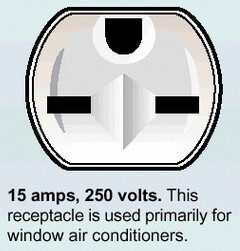
Input 3: CT3 on a 240V circuit supplying my air conditioner. I would need to configure this differently than CT1 and CT2. I think this input would need to use the sum of the absolute value of the L1 and L2 signal.
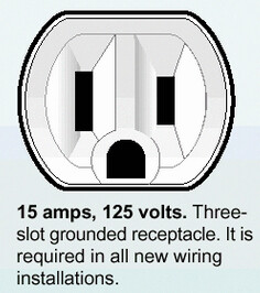
Input 4: CT4 on a 120V circuit for some other appliance. I would need to identify if this circuit was on L1 or L2 and configure the input accordingly.
It’s just an interesting thing to contemplate. In the past it was not necessary to configure which voltage signal was applicable because there was only one. In the future it strikes me that it will be necessary. And that’s my question. It will be, right?
Sets the relationship between voltage and current inputs to enable the calculation of real
power. For single-phase, one leg of a split-phase and 3-phase 4-wire measurements,
voltage and current sensor must be on the same phase/leg. The second voltage is needed
only for the line-line power calculation in split-phase and 3-phase systems; i.e. when the
current measured is line-line.
Here’s how Sense measures both legs’ Voltage. I don’t know enough about emonVS or US electrical codes to know if it’s viable for you guys, but there’s probably enough collective knowledge here to work it out. If it does suit, it seems a pretty cost effective solution.
The problem that the emonVs has is the v.t’s are permanently connected in star, with the star point being the neutral (line 1 and neutral also being the power supply to the encapsulated 5 V psu) - presumably to save two terminals, so when a line-line power measurement is required, the calculation needs two shifted voltage samples to derive the line-line voltage. This implies a significant reduction in the sample rate. I think there isn’t a plan to handle the 3-phase, 3-wire 220 V system that I believe still exists in parts of France and Belgium, and in parts of Scandinavia.
I wasn’t referring to the product as being cost effective… until your post just now I didn’t know the price. I meant a cost effective way to tap into the two legs for the purpose of measuring both Vs. Presumably a sparkie is going to charge you less to install a 240V breaker than he would to install a 240V breaker and a 240V outlet.
But I think the entire emonVS and emonTx would then need to fit inside the breaker box. I don’t think that will happen to most people. Once you move the devices outside the breaker box, the outlet is a good way to go.
This might be my ignorance of the emonVS setup is showing, but isn’t there a cable running between the two? Could you not treat the emonVS as just another sensor, alongside the CTs… then wires would run from all of the sensors out to the emonTX?
@Bill.Thomson might know what the insulation requirements are for wires coming out of the panel.
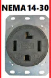
Yes, it does need 4 pins, A & B legs, Neutral and Earth.
Indeed there is - and it’s 5 V maximum inside, referred to earth. The only requirement that I can possibly think of is it will need a physical barrier between it and the 120 V wiring - which should not be difficult as there’s quite a distance between the two groups.
IIRC, wires carrying the lowest voltage are required to have insulation rated the same as
that for wires carrying the highest voltage. Given that’s 240 Volts, (in this case) and the use of 300 Volt rated wire is very common in the US, that shouldn’t be an issue.
The “gotcha” is mixing LV and HV wires in the same conduit is a no-no.
There’s no marking on the flat “output” cable to indicate a voltage rating - not surprising really. I doubt it is 300 V though. @glyn.hudson should be able to tell us. I suspect it is 150 V.