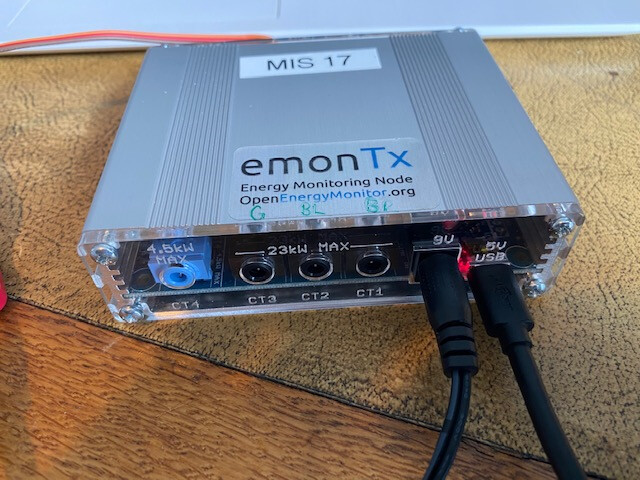
@borpin is your emonTx connected using the 9V AC and the 5V USB DC per my photo below:
I am running the emonTx_3Phase_PLL sketch (with node id 17) and have edited emonhub per the below:
### This interfacer manages the EmonTx3 ESP format serial
[[SerialTx3e]]
Type = EmonHubTx3eInterfacer
[[[init_settings]]]
# Un-comment line below if using RS485 adapter
com_port = /dev/serial0
#com_port = /dev/ttyRS485-0
# default com port if using USB to UART adapter
#com_port= /dev/ttyUSB0
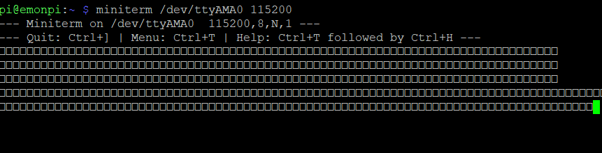
com_baud = 115200
[[[runtimesettings]]]
pubchannels = ToEmonCMS,
[nodes]
## See config user guide: https://github.com/openenergymonitor/emonhub/blob/emon-
pi/conf/emonhub.conf
[[17]]
nodename = emonTx_three_phase17
firmware = three_phase
hardware = emonTx V3.2/V3.4/Shield
[[[rx]]]
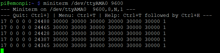
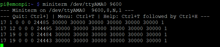
names = power1, power2, power3, power4, sumPower, Vrms, temp1, temp2, temp3, temp4,
temp5, temp6, pulsecount
datacodes = h, h, h, h, h, h, h, h, h, h, h, h, L
scales = 1,1,1,1,1,0.01,0.01,0.01,0.01,0.01,0.01,0.01,1
units = W,W,W,W,W,V,C,C,C,C,C,C,p
I have the following in the sketch:
[[17]]
    nodename = emonTx_three_phase17
    firmware = three_phase
    hardware = emonTx V3.2/V3.4/Shield
[[[rx]]]
    names = power1, power2, power3, power4, sumPower, Vrms, temp1, temp2, temp3, temp4,
    temp5, temp6, pulsecount
    datacodes = h, h, h, h, h, h, h, h, h, h, h, h, L
    scales = 1,1,1,1,1,0.01,0.01,0.01,0.01,0.01,0.01,0.01,1
    units = W,W,W,W,W,V,C,C,C,C,C,C,p
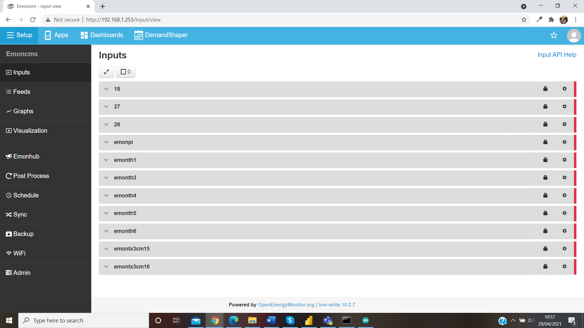
I’m not getting anything through on emonhub though:
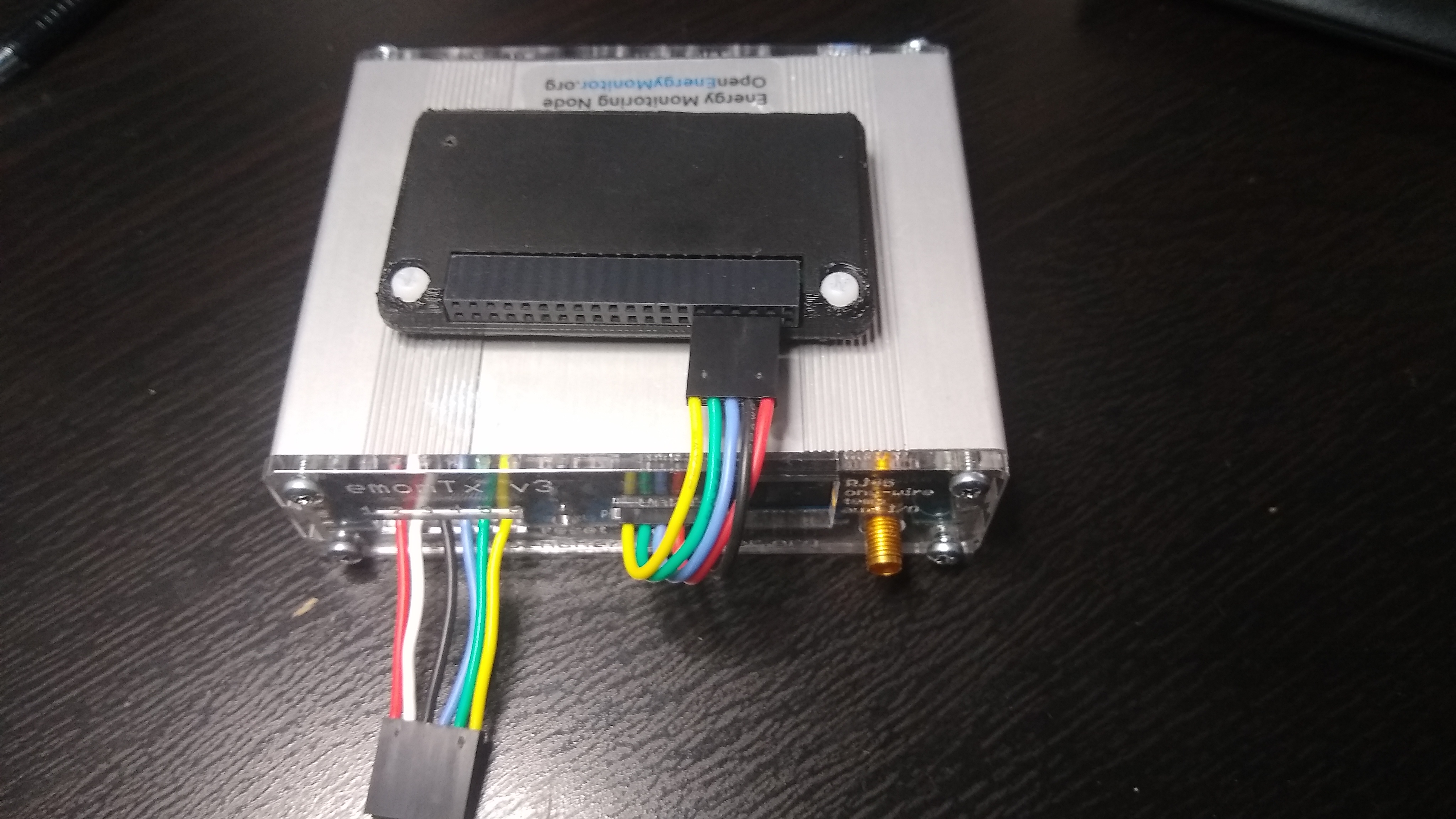
I’m currently testing this on a Pi4 as my Ethernet dongle stopped working yesterday so can’t connect my PiZero until a new one arrives. So I have the Pi4 powered up using the USB-C port and the emonTx powered up using the 9V AC. I then have the 3x jumper leads connecting the two (with Rx from the emonTx into the RXD on the Pi4). I don’t have the 5V DC plugged into the emonTx. If I do plug in the 5V DC and take out the USB-C from the Pi4, it doesn’t have enough power to run the Ethernet port.
 .
.