Hi, I have an emonPi, and 4 emon TX’s.
Two TX’s are between 4 and 20m from the emonPi, and two are right next to it.
One of the Tx’s that is next to the Pi, seems to stop sending data every week or two. As soon as I press the reset button on the Tx, it starts sending data again.
I was thinking of connecting the reset line on the Tx to a spare IO on the Pi and resetting it every 24h with a cron job.
That seems a bit brutal, and not really addressing the issue.
What debugging can I do on the emonTx? If I connect to the serial port is there some debug / bootup data that will tell me the firmware version.? Perhaps a firmware update might resolve this?
Yes, it should tell you at startup.
I’m not aware of a recent (i.e. in the last couple of years) software problem that might account for this behaviour. So by all means check and update the software, but I think it’s more likely to be a hardware fault. If you can leave a serial monitor on the faulty unit, what you first need to establish is whether the sketch locks up, or whether the transmitter stops sending. The serial output stopping or not will tell you - so will the LED flashes, if you can see it.
OK, I’ll see about getting a serial port on it, and make a note of the LED next time it does it.
It just hung again (no data getting to emonPi (other Tx’s OK).
The LED on the hung emonTx was not flashing. So does that show the software did hang?
Was the LED definitely flashing when the emonTx was working? The significance is in the LED stopping flashing. No LED could also mean the AC:AC wasn’t present at startup.
What is your power supply setup?
The ideal set up if you have 2 emonTx’s next to an emonPi is to power all 3 from the same 5v AC:DC and use a single AC:AC to provide a reference voltage signal to all three (assuming a single phase setup, 3 AC:AC’s if 3ph). This would possibly use less sockets, consume less power and provide both a better power supply to the emonTx’s and a better AC waveform too.
Do you have any other sensors attached to the emonTx in question? eg temp sensors or pulse counter.
Did you find out the FW revision?
Is there any possibility of a poor power supply connection that is getting disturbed/reset when performing the “reset” to the emonTx?
Hi Paul,
I have 2 Tx’s and the Pi all with the same AC ref from the one plug pack, and all powered by separate 5V USB plug packs.
The Tx’s are jumpered so they don’t draw power from the AC.
The Tx that does not have a problem has a temp sensor, but not the one that has probs.
The LED’s on both do flash when they are running normally. I’ve not got the fw version yet.
I could try swapping the 5V power from one Tx to the other, if the problem is the connector or plug pack, that might make the issue move to the other Tx?
That would be a good step.
If this does pan out to be a hardware issue, it may well be that there is a poor connection (cracked/dry joint) to the RFM module, I wouldn’t say it’s common but we have seen it before. If you do find this to be the case, rather than adding a reset line from the emonPi, you would be better off modifying the sketch to not use the RFM and add a FTDI usb serial adapter to the emonTx so you can connect it to a usb port on the emonPi, same number of wires (emontx connected to emonPi instead of PSU) and no automated resetting.
I’ve swapped the usb power, so we will wait and see what happens.
I’d like to remove the RF for the Tx->Pi link, but I have two Tx’s co-located with the Pi. Is that still possible?
Would that involve software mods on both the Pi and emonTx? The Pi is easy, the Tx slightly trickier. I believe the Tx is aurduino based? I’ve used esp8266 modules before, so it’s not out of the question to customise the Tx software.
Yep, There are many posts on doing this type of thing.
The most common is the “serial-direct” method which connects the serial port of an emonTx to the serial port on the Pi’s GPIO, but that is not possible on an emonPi because the emonpi board is already using the GPIO serial port.
The alternative “serial-direct” method of connection is to use a usb to serial converter attached to the emonTx serial port and using an USB port on the emonPi, this is configured exactly the same way as the above except the serial port defined in emonhub.conf will be something like /dev/ttyUSB0 rather than /dev/ttyAMA0.
The slight difficulty comes when connecting more than one emonTx to the emonPi via USB, because of the way the /dev/ttyUSB0 and /dev/ttyUSB1 addresses are dynamically issued at boot time on a first discovered first served basis, so one day emonTx A could be /dev/ttyUSB0 and emonTx B would be /dev/ttyUSB1, after a reboot it maybe the other way round, as long as the emonTx’s are passing a node Id as part of the payload this shouldn’t matter much, but the default sketch on the emonTx does not include the node id in the payload. So there are 2 ways to handle this and that is to change the sketches to send node id and not care about the “/de/” addresses or you can specifically buy FTDI FT232L usb to serial adapters which have unique identifiers and add a simple udev rule to the emonPi so that the emonTx (or rather their respective serial adapters) are always recognized and addressed the same way.
I regularly use the latter method to build 3ph monitors that do not rely on RF, I mont the serial adapters on the emonTx boards where the battery holder is currently, with a double sided sticky pad and connect all 3 to a Pi 3(not an emonPi) See the Does the emonTx Shield need an actual Arduino? - #18 by pb66 thread for some more info and pics.
Probably more suited to your application I have also installed some single “usb converted” emonTx’s that are cased with the FTDI adapter slightly more in-board so a USB lead can be attached and led out of the casing by drilling a hole in the perspex end, close to the edge and “slotting” it to the edge with a couple of short hacksaw cuts.
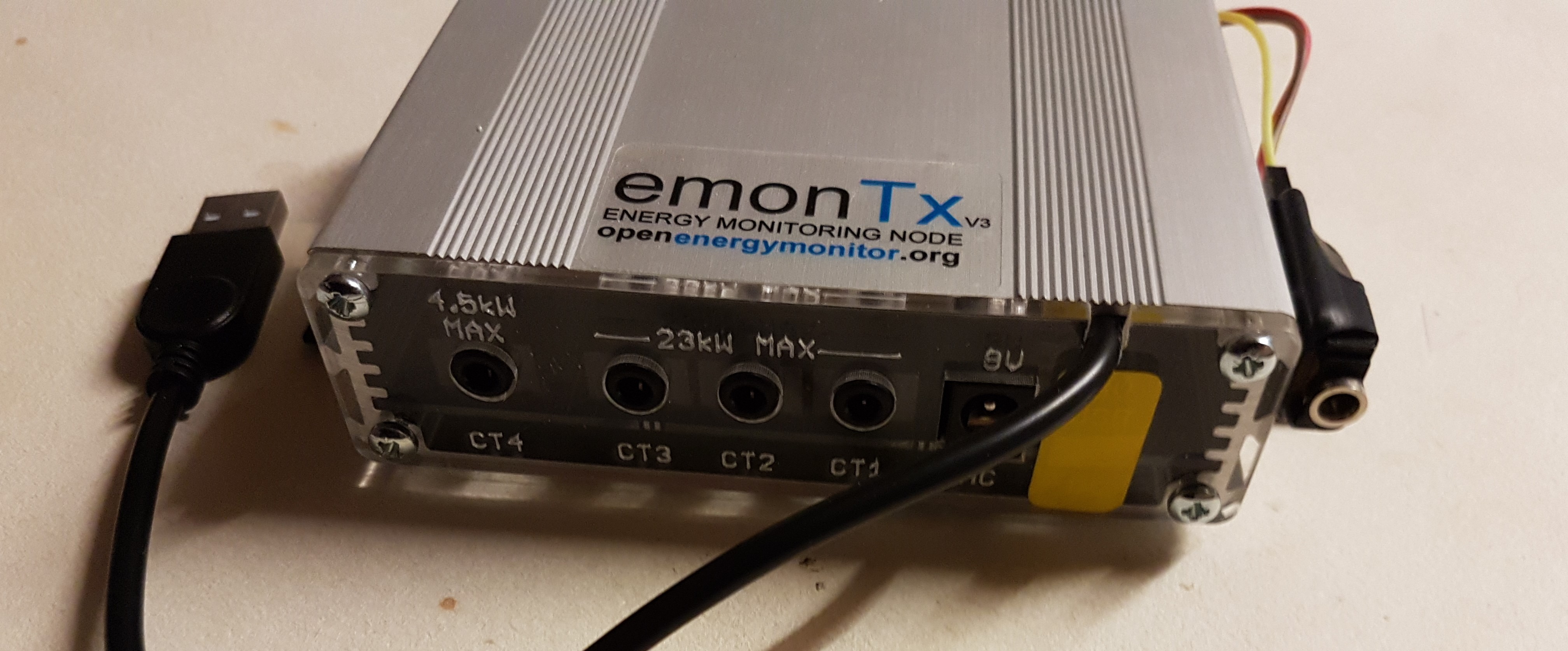
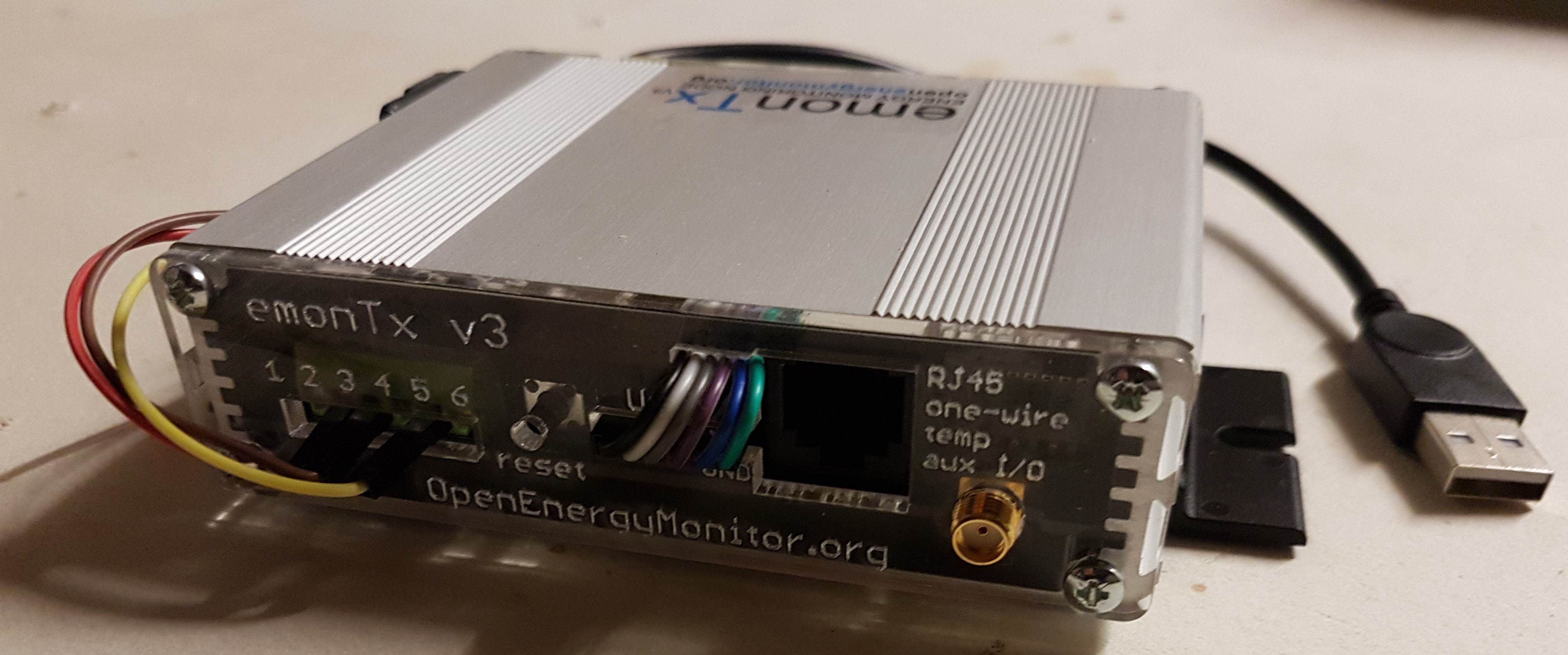
In the lower pic you can see I have also cut a slot for the 6way ribbon cable, I chose to do it this way rather than connect inside the case so the original connector is retained and accessible without a screwdriver.
[ignore the red, yellow and brown wires and the extra socket stuck on the side, this one is also converted for 5 CT’s. ]
Thanks Paul for all the info. I might have to look into the FTDI method you describe. Cases are not an issue as I have bare boards to be mounted in a much larger box under my switchboard.
So with multiple Tx’s you need to use a USB hub to connect to the Pi?
No not specifically, an emonPi has 4 usb ports and the emonTx’s draw so little that a powered usb hub isn’t needed, so unless you need more than 4 emonTx’s (or have the usb ports already occupied) you can just connect directly to the emonPi.
Hi Paul,
So it’s been 7 weeks, and the TX finally crashed again. Red light not flashing. This was after I swapped the power supply and USB cable with the other co-located tx. So the issue is definitely on board.
I suspect I’ll need to replace the board, but as a last ditch test (in case it’s RF related), and 'cos it would be useful to take the RF out of the equarion (as the two TX’s are mounted right next to the emonPi anyway), I’d like to try to direct connect them rather than use the RF.
You mention using a FTDI FT232L usb to serial adapter and udev rules on the pi to force the enumeration order. Can you recommend an example unit, and provide examples of the udev config?
Also, are you able to point be in the right direction re details of the software chanes needed on the Tx and emonPi ends, and where you connect the FTDI on the Tx?
Cheers,
Michael.
If you are only connecting one emonTx via serial USB, you wouldn’t need to write udev rules, if you think you may connect more emonTx(s) via serial USB I would still recommend using an FTDI based adapter just in case (saves ditching a non-ftdi one when you hook up a second device).
There are several threads on “serial-direct” connected emonTx and this “Does the emonTx Shield need an actual Arduino? - #21 by pb66” thread might give you some info on sourcing and connecting a ftdi usb serial adapter.
[edit] Since the emonTX RFM is possibly stalling things you may need to edit the sketch to remove the RFM bits so that it doesn’t stop when using a serial adapter, in which case you can edit the sketch to send the node id as part of the data packet, so you could get away with using an OEM shop sold USB adapter.
if you get an adapter (and leads?0 we can walk you through the changes, it’s not that difficult.