3x CT unberdened, taken care of by the resitors ^
https ://www.aimdynamics.com/product/sct-1250_split-core-ct/?attribute_pa_amp-rating=no-burden-resistor
$48.00 each
$144.00 total (£114.25)
Grand Total: £ 414.375 – £ 331.5 ex VAT
man that added up quickly
A quick question, does it matter where I pull the sockets (for the AC-AC adaptor) from, I ask because we have a 3 ‘circuits’ coming off the bus bar going to different production areas, the goal is to measure the the total, so the CT will be placed right before the main circuit on/off switch (between the meter and the bus bar), but do the adaptors matter say if i have them coming off a specific circuit, I’m hoping it doesn’t matter as this makes placement much easier!
I think your burden resistor is a little high. When you subtract allowances for component tolerances etc from the 3.3 V peak to peak, I get 1.1 V rms as the value to design for. That gives me 41.26 Ω, so I would go with 39 Ω, giving you a little over 210 A maximum current. With your 43 Ω burden, I could not guarantee undistorted readings from a pure sine wave above 192 A. If that’s OK with you, fine.
Not really. You want them on a circuit where there are no large loads and as close as possible, so that there is minimum voltage drop in the cable between the bus bars and the ac adapter.
If you don’t have a programmer, you might want one to reload the sketch after you’ve changed the calibration values, which will be wrong because you’re using a different CT and burden. Alternatively, you can calibrate in emonhub.conf (local emoncms) or put a multiplier in the processing chain in emoncms.org.
OK, I thought as much, but does the load on the the bus bar be the same as that of all the 3 circuits. Initially i was going to have a 4th breaker box direct from the bus bar just for these sockets… but if what i say my understanding is correct then would it matter since the other 3 circuits are still coming from bus bar… maybe I’m just confused here
I attached a picture for easier understanding as my wording could be incorrect :s
1 and 2 here are the main consumers, 3 powers stuff like office sockets / lights ect… so to keep the costs down I was thinking of pulling the sockets from their own Circuit breakers coming from number 3 which is about 2 meters away.
Then the alternative was adding a 4th box (in this case a circuit breaker one) straight from the bus bar…
If distribution board 3 only has “office lights and sockets” you should be fine taking the 3 sockets from there, 1 and 2 may be slightly less suitable depending on how heavy the loads are on them, but 3 is close enough (electrically) and unlikely to have a voltage drop of any significance.
When installing those sockets you should consider hiding them away in an enclosure.Tthis is not only tidier and less likely to get unplugged, it is also safer and less likely to contravene any regulations (or bad practice) about having sockets from different phases in close proximity due to the potential 415v across any 2 sockets in a fault condition.
I have installed a fair few 3phase systems and I usually do something like this (excuse the 4way extn lead, this pic is from the test bench not installed on site)
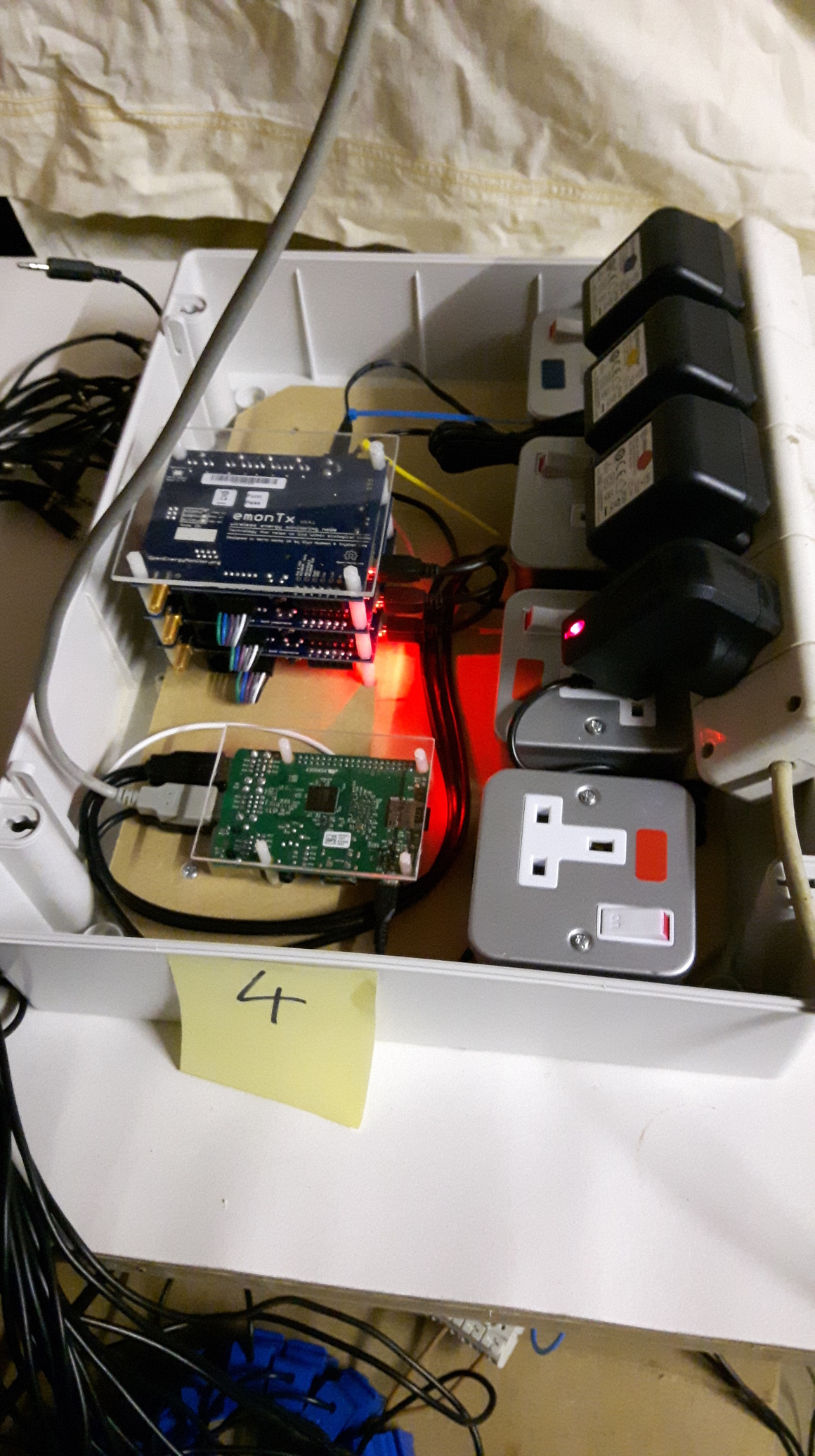
Although I have now progressed to using 2 smaller enclosures to separate the high voltage stuff from the monitoring electronics as it is more flexible to locate than one big box and the Pi runs cooler without the heat from the 4 PSUs
This is a later monitor box, the 4 sockets (2single + 1double for the 5vdc too) are now put in a separate box by the sparkies doing the electrical install.
ohh thats a nice setup, I was planning a similar thing too putting them all in nice contained box, but i need to get all the technicals out the way first hehe
Yes, that particular circuit is mostly stuff like that… tho I believe there are some bigger things hooked up to it now, think some heaters were added… but it is the lowest load out of the 3…
I see you have your Tx powered by the base… interesting, any reason for this? why not just use the AC adaptors for both?
As Dave asked, you using wireless modules or the serial coms, I initially wanted this, cause its cheaper (no wireless module needed) and since everything is close no real requirement for it…
Hi Dave, I currently use a separate serial interfacer in emonhub, for each emonTx. They will usually get automatically addressed as /dev/ttyUSB0, /dev/ttyUSB1, and /dev/ttyUSB2 but have no control over which is which (not so good!!!) but as long as the node id is written into the sketches payload this isn’t a problem until you have other USB devices and the addressing range gets altered.
I use FTDI serial adapters with a writable eeprom and have added udev rules so emonTx’s are automatically recognized and use their own serial numbers as addresses e.g.
pi@emonBase5(ro):~$ ls -la /dev/emon*
lrwxrwxrwx 1 root root 7 Oct 11 16:21 /dev/emonTX-TX4O3K2 -> ttyUSB1
lrwxrwxrwx 1 root root 7 Oct 11 16:21 /dev/emonTX-TXPTU5K -> ttyUSB2
lrwxrwxrwx 1 root root 7 Oct 11 16:21 /dev/emonTX-TXTNIZG -> ttyUSB0
because I am using USB=>serial for comms so there is a 5vdc connection to be had, powering the emontx via the 9vac can have a slight impact on the voltage waveform, not necessarily enough to justify putting in a separate 5vdc in most instances, but since it’s there it is the better option.
The real benefit is the 100% success rate for getting all data, 3 emonTx’s on the same RF network will result in lost packets, due to having almost exactly the same time intervals, when 2 emonTx’s clash timewise it can take half an hour for the clashing to pass depending on the send interval, length of payload and the accuracy of the interval timing.
3 serialUSB adapters and leads is not really any cheaper than an rfm2pi receiver, but the data is much more reliable.
Hi pb66, could you possibility go into detail into this? the wiring part at least Serial as in using the UART connections using something like usb to serial? I was trying to see how you got this plugged in from the TXs to the base but couldn’t quite tell from the pics, i see some cables coming out of each Tx but cant tell where/how they get to the base
The USBs coming from the base, are just powering the TXs right or you have some split somewhere leading to the serial adaptors?
EDIT
ohh wait, i think i get, you’ve go those connected to those adaptors hidden under the boards (I noticed USB is not the one in the Tx) and that also takes the 5V input as you mentioned.
The shop sold serial adapter/programmer is based on a SiLabs CP2101 chip, the ones I use are based on the FTDI ft232rl chip which has an eeprom, this is important if you wish to simplify the connection and identification, it is not impossible with other serial=>USB devices but the eeprom and id number make it much easier.
“FTDI” is a brand, although “FTDI” has become an unofficial generic term for a USB=>serial adapter.
Here is a pic of the emonTx stack flipped over, I remove the battery holders and use a double-sided stickey pad to attach the FTDI.
Because you can only connect one device to the one serial uart on the gpio, not 3. And sometimes I also install several emonTH’s and/or remotely located emonTx’s, so I can still add an RFM69Pi if I choose, and the 3xsingle phase boards are all connected the same way.
That sounds like a lot, how have you saved that much?
The 3x FTDI and 3x USB leads may well cost significantly more than the one RFM69Pi, unless you take a chance on cheaper Chinese ebayers, which could save you money or cost you 3weeks when you have to get a refund as they are fakes, believe me I know!
i would recommend using ebay over Amazon as their buyer protection means if you order something that says “Chip: FT232RL” and it turns out not to have an eeprom, ebay will guarantee a refund, Amazon is not so quite so accommodating, it is down to the seller.
Verified Purchase
Does not work - the chip is a counterfeit, and so it gets “bricked” by the FTDI driver (see this article for details: […] After connecting it to my machine the USB PID of the chip gets set to zero, i.e. the thing has been killed