But this set-up is used to be plugged into the GPIO slot of a Raspberry.
I’d like to use the RJ45 input of the EmonTx.
So my questions are:
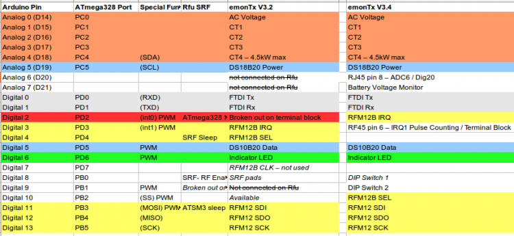
Is the RJ45 input only for analogical sensors (such as the DS18B20) and pulse sensors (such as the Optical Utility Meter LED Pulse Sensor), as detailed in EmonTx V3.4 - OpenEnergyMonitor Wiki . Or can I use it for serial data sets ?
Is the RJ45 connection which is on the EmonTx provides a GND, a 3.3V and a data wire?
Will I have to update the Arduino in the EmonTx in order to send the data to my EmonBase, or can I do the process of the data sets directly in the EmonBase?
I would advise you download the full circuit diagram from emontx3/hardware at master · openenergymonitor/emontx3 · GitHub
Get both the PCB layout and the Schematic - be certain to download the raw file, not the screen view. You will also need to download and install Eagle CAD (free!). It is painful the first time, but you then have the drawings used for manufacture.
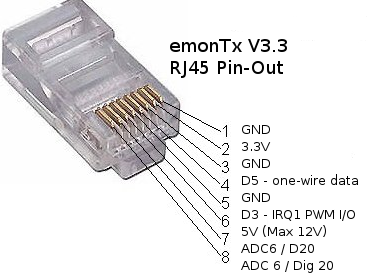
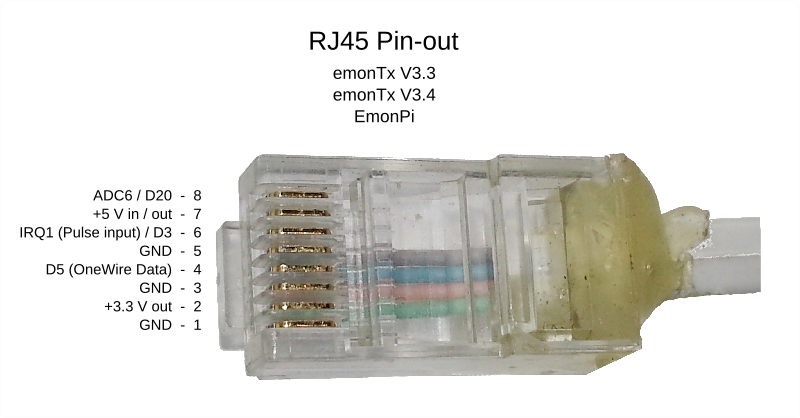
The RJ45 pin-out picture is wrong. Here is one I did earlier:
Then I understand that the D5 (Dig 5) is connected to the PD5(T1) on the ATMega. It can be connected either with the RJ45 port (pin #4)or the 6 pin port (pin #6)
So I believe I have to connect the RX data wire to the D5:
From the link about the Teleinfo output, I think the meter is sending the reading as a serial data stream.
What will your emonTx be doing in addition to receiving this stream of data?
The problem I foresee is, the serial data stream must be accurately read and interpreted by the emonTx, and that means that the emonTx can do very little else while that is happening.
Do you have a sketch for the Atmel 328P that will read the Teleinfo data, or are you planning to develop one?
Do you mean that the EmonTx won’t be able to deal with other inputs or sending data to the 433MHz, because of the resources needed to compute the serial data ?
So I would like to adapt some of these codes to make it work within the EmonTx.
Actually, I don’t mind using Python on the EmonCMS side to decode everything I can.
I prefer not to change anything in the EmonTx but I’m not sure that’s possible…
I am assuming that you will merge the Teleinfo sketch and our emonTx sketch, and you can use the serial data port - see below.
I think that if you use the “Discrete Sample” sketch, and if it is necessary to tell the meter to send data, or if the meter sends the data automatically but there are big gaps between messages, then I think it will be easy. But if there are no gaps, you will need to modify the Teleinfo part to discard the data while the “emon” part is working.
But if you use the new “Continuous Monitoring” sketch, there is a real possibility that the processor will not be able to receive the data and do the “emon” measurements at the same time. The only way you will find out is by doing it. If that is the case, then doing the Teleinfo in a separate Arduino Nano will be the easy way.
I think it is possible to use the serial port for both for the programmer to upload your sketch, then by changing the connection to use your opto-coupler. But I do not know exactly how you manage the change.
I do not know if it is possible to receive the serial data using a normal digital input instead of the dedicated RX port. See https://www.arduino.cc/en/Reference/SoftwareSerial which seems to say it might be possible, using the interrupt (pulse counting) pin on the emonTx.