Just got my new emonbase and emontx v3 connected, with emontx running on 3 AA batteries. I’ve added the feeds ok, but emontx is only intermittently reporting valid values. It keeps reporting zeros, then some valid values then zeros. Have I missed something in the setup? The batteries I’ve put in are rechargeable. Is it continually rebooting because the batteries are low or something? The spec for emontx says you can remotely monitor battery level. Is there a link that shows how to do that?
Note, I was charging an electric car at 4.4kw at the time so the 4k+ values received sound right.
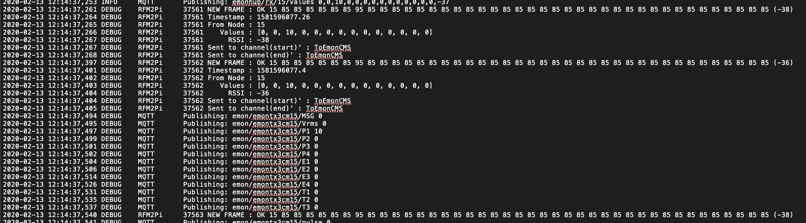
So it sends the numbers 10 down to 0 with 100 ms delay between them.
It should do that once. If it’s doing it all the time, it could be the battery voltage is too low - or the cells’ internal resistance is too great - to sustain the current needed to transmit, or it is the watchdog firing. The first is very likely to be causing a reset, the second certainly will.
I’ve never tested on batteries, so I can’t confirm that. 3 × 1.2 V is however pushing your luck, so that’s the most likely cause.
The sketch you’ve got is specifically for non-battery use, so it doesn’t report the battery voltage. If you’ve got the appropriate USB lead and a phone charger, or you can temporarily run a mains lead out to your meter box and connect your a.c. adapter, it should work correctly.
I ticked the box for the 3 AA battery holder when ordering the emontx which, according to the shop, means it comes pre-installed with the low-power consumption firmware for use with batteries. I’ve switched to 3 brand new duracell 1.5v batteries. It is better but still intermittent. I’ve got 3 CTs and the optical pulse counter. When I disconnect the pulse counter it seems more stable, so perhaps the batteries can’t supply enough power to handle the pulse counter.
Is there a way to tell if I’ve got the battery firmware installed? Is there an extra feed available with the battery firmware?
You do in fact have the “DS” (Discrete Sample) sketch - the last line of the screenshot was covered up by the caption - and that’s where the difference is. The test output is the same for both.
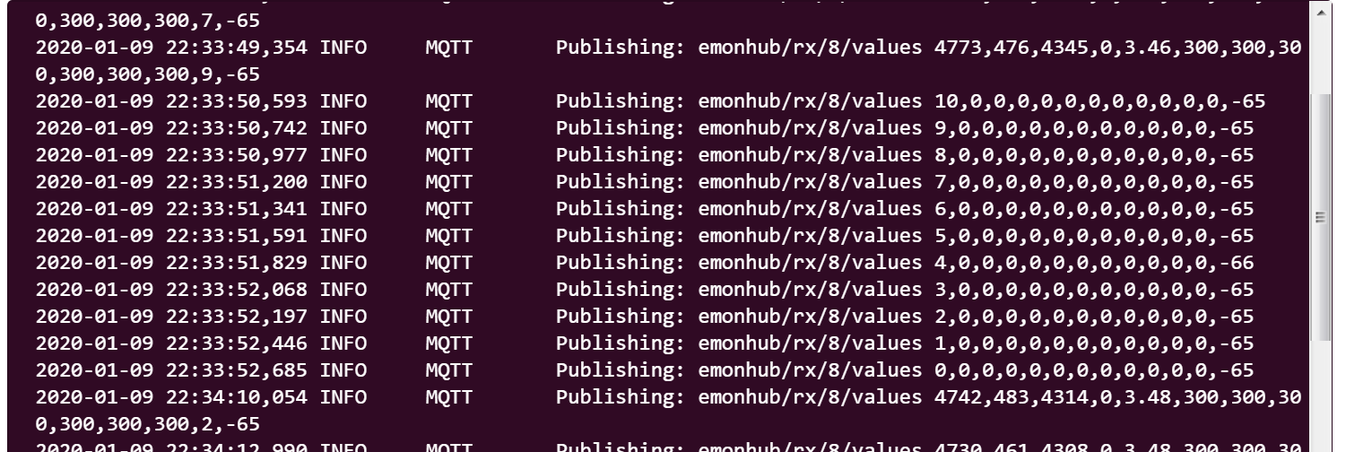
In that case, the battery voltage is reported in the “Vrms” slot, which is the 5th variable, 3.48 in your case. It switches to reporting battery voltage if no a.c. input is detected at start-up. 3.48 V is OK for rechargeable cells, but low for alkaline.
The optical sensor takes no current normally, but (according to the shop web page)
Current Consumption - Pulse: 7.5mA @5V for duration of pulse (standard meter 100ms)
3 new alkaline cells should be able to support that, so I’m rather struggling to see why it’s falling over. Unfortunately, my emonTx V3.4 and optical pulse sensor are in use for a test for the next few weeks, so I can’t make any measurements using it.
Are you able to give it a temporary mains supply? The reason I’m keen to see what happens then is there are two separate power supplies: the 5 V USB, FTDI programmer and battery holder feed into a MCP1702 regulator connected directly to the 3.3 V used by the processor and radio, whilst the a.c. adapter feeds into a MCP1754 that feeds into the 3.3 V via JP2, the link right next to the battery holder.
I’m starting to wonder whether you have a high resistance joint somewhere - either in the battery holder itself or a badly soldered joint on the board.
That’s definitely something I’ve not heard of before. Did you notice whether the resets coincided with a pulse from your meter - it certainly looks like that could be what’s happening.
A lot of people have used the optical pulse sensor with that sketch, so I think we can discount a programming error. That leaves a faulty pulse counter or a faulty emonTx. Unfortunately, I can’t think of a test you can do to find out which is faulty - it might even be both as removing the pulse sensor when running on batteries didn’t make the problem go away. I think it’s time to email [email protected], and mention this thread.
How much “more stable” is it with the pulse counter disconnected?
Does it stop resetting entirely?
Can you confirm how frequent the data packets are when it is running? Perhaps attach a emonhub.log that spans 2 resets. The packets should be every 10s but maybe much faster in this instance.
But the mainstream “master” firmware has since moved on with (another) v3.0 (Zero unused CT’s), v3.1 (serial config prompt) and v3.2 (watchdog) so maybe the installed “battery friendly” DS firmware is currently still not “pulse counter friendly” when running on batteries perhaps, and the symptoms have morphed due to the later addition of the watchdog.
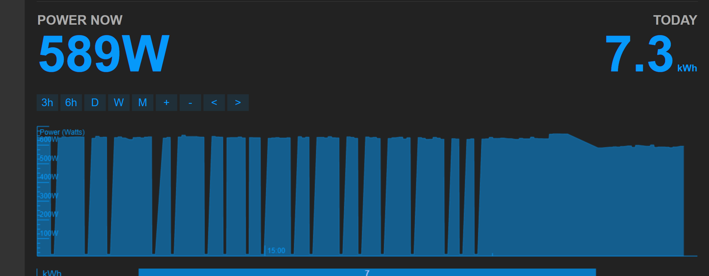
I can confirm it seems completely stable without the pulse counter and regularly resetting roughly every 90s with it.
My meter box is on an external wall and has no room inside for sockets anyway. It would be quite a job to get permanent supply to it, hence the need to run off batteries.
Looks like the battery_pulsecount branch never got merged in, good find @pb66. It’s been 3 years since that work was done so would need revisiting and may take some time. Your welcome to try that branch of the firmware if you like in the mean time @richy1995, do you have a USB to UART programmer?
Yes, I do have the USB to UART cable. I’m a bit of a novice with git though. When I tried to “clone https://…emontx3/tree/battery_pulsecount” the repository wasn’t found. I did manage to “clone -b battery_pulsecount https://…emontx3” if that’s what you meant?
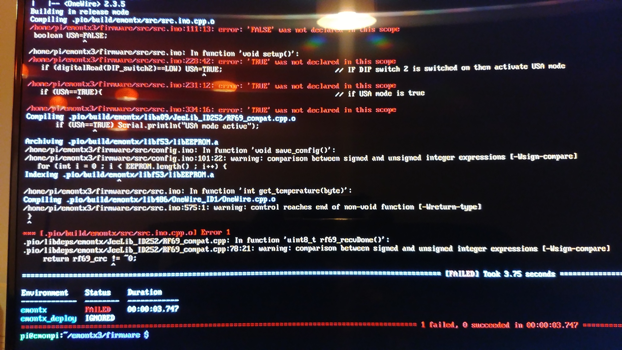
Then I ran “$ pio run”, but it failed.
I edited my copy of the src.ino file to change TRUE and FALSE to lower case and tried it again and it compiled and uploaded ok. Seems to be running ok now without resetting. Thanks for your help guys.
I seem to be getting similar problems, however not using batteries…
I recently added a second emonTX3 purchased with Node 16 (and CM of course), to monitor extra circuits. I have also updated my emonPi to emonSD-17Oct19. The new emonTX3 seems to operate largely correctly, although it does need calibrating (later…).
My “old” emonTX3 is board rev 3.4.2. I decided to upgrade this to CM firmware, and this is where things started to go wrong (there is a moral here). I am using MacOS (10.11 El Capitan, oldish) and Arduino IDE with a new USB UART cable. I am new to THE Arduino IDE so be gentle please! Fortunately there are many tips and guides on here.
With the IDE connected, everything seems to work pretty well, although there are occasional frame dropouts. I thought this might be RF interference as I have quite a few other 4333mHz transmitters around the house… A problem for later.
HOWEVER, If I disconnect the IDE, the emonTX3 now continuously transmits zeroes which ties up emonhub completely:
It looks like the EmonTX is continually resetting itself? Yesterday it was working normally - without the IDE connected - for most of the time, then went into this state occasionally. Now it seems eminently repeatable. Which is (probably) good, sort of.
I may be doing something idiotic with the IDE and its connection/disconnection?
Also I cannot get it into Config Mode at startup, despite trying everything I can think of. Here is the startup sequence… Untitled.txt (1.2 KB)
That all looks OK. But it didn’t accept “+++”? Have you got the IDE set to send “Both NL & CR”?
There’s no obvious reason for it sending zero values. @TrystanLea wrote the sketch, so he might have some ideas. The mains voltage isn’t reported as being low, so while I don’t immediately rule out a power supply issue, it doesn’t look very likely.
Arghhh. IDE was set to NL! I was reassured by the fact that the “l” command was working whilst it was running! Odd that “l” works with NL setting but “+++” during startup doesn’t. Will have a look at the code when I have a minute.
OK I have Config Mode working. Thank you. I have done a Reset of EEPROM.
I was looking at this thread (EmonTX Calibration Safety) regarding AC-AC power concurrent with USB-UART. Initially I disconnected the AC-AC charger to load the new sketch, but have left it connected subsequently.
When I disconnect USB-UART the Emontx reboots. Presumably this is normal behaviour?
I think I found the reason. In config.ino the line that tests for “+++” input is: if ( Serial.readString() == “+++\r\n”)
i.e. explicitly checking for CR NL,
whereas in the main loop the code is simply Serial.read();
followed by a switch/case statement testing for a single char, so CR NL is not necessary.
It’s not a big deal, just inconsistent UI. And it caught me out
I can’t say that I’ve ever noticed. I don’t think it’s intentional, but the reset line is in the connector and is controlled by the UART (to put it into programming mode to load the sketch), so I can well believe that if you pull the right-hand end off first (the GND pin is the right-most, Reset is the left) you could get a reset and hence a restart.
Thanks Robert. I tried again to run the emontx3 without USB-UART power, it ran for an hour or so before going beserk again.
I have now swapped AC-AC PSUs between the old and new emontxs, and see how long that goes for.
I noticed the CM firmware doesn’t pulse the LED during transmit every 10s. Is that deliberate? Incidentally, the emontx LED goes full on when it goes into beserk mode and floods emonhub.
That’s useful information. The LED is turned on almost immediately as the sketch starts up, and is turned off after you’ve gone through (or past) the user configuration and it’s checked which c.t’s are present, but before it reports the findings. So, if the sketch does restart, I’d expect the LED to stay on for 10 s. During that period, it does transmit the factory test sequence of Power1 having the values 10 to 0 in steps of 1, in rapid succession. Is that the behaviour that you see?

 Thanks for your help guys.