Emon for 3-phase PV system and house in Italy?

I’m a Brit currently living mostly in Italy, but also with a house in the UK. Here in Sicily, I’ve a 3-phase 10kW-rated PV system, and a 3-phase house, while my UK house has a single-phase 2.4kW rated PV system, and is single-phase. Both PV systems have been in place for 10 years.

My UK house was recently switched to a Smart Meter, and I’m pleased with the operation of the In-House Display, showing me if I’m net exporting to the grid, or importing from it. I’d like something of this sort here at my house in Sicily, which I hope an OpenEnergyMonitor solution could provide, but it is not clear to me what exactly what I would need to acquire, or could expect to achieve.

I do currently monitor and record PV production, using the windows-based software provided by the manufacturer of the inverter (via an RS-485 cable from the inverter to an old laptop), and a spreadsheet. I cross-check generation totals against those registered by the generation meter (for incentive payments). However, I have nothing to show energy consumption, as the UK IHD does, and this is where I would hope emonCMS, showing both production and consumption, would fill the gap, as well as provide me with a data history.

While I can envisage what would be needed for an emonPI installation at my UK house (in the cupboard under the stairs), I have somewhat more difficulty envisaging what I would need for my 3-phase 4-wire house here in Italy, where the PV installation is on a structure at the end of the garden, and the consumption meter is outside on the street. If I understand correctly, I would need an emonBase and emonTX, and the system would measure voltage on Phase 1 only (extrapolating for the other 2 phases?), but export/consumption on all 3 phases. Does this mean I would need 4 CT sensors in total, and a single emonTX? Could anything more be achieved with a second emonTX (I think I read two is the limit for such a system), or would anything extra potentially gained not justify the extra cost and complications?

I have put the potential idea of such an installation to the Italian electrician who installed the PV system ten years ago, and he seemed intrigued and interested in such a non-invasive solution. I showed him the diagram of the type-2 single-phase installation, and he asked me to provide a 3-phase equivalent (which I don’t think is extant), but also identified where he thinks the hardware could go. I myself am not from a technical or scientific background, but have some Linux experience, and own a raspberry pi myself. I am also fluent in Italian, so should be able to communicate anything necessary to the electrician, though any computer-related setup would be down to me. The ultimate question is, would the combination of he and I be able to deal with anything not strictly out-of-the-box to get such a system up and running with a fair degree of accuracy?

Given these limitations, does setting up a 3-phase energy monitoring, generation and consumption system here in Sicily sound easily doable, or is a fair degree of technical ability necessary for setup and calibration?

Welcome, Alan, to the OEM forum.

I think you’ve got the general gist of things - in the most general terms the 3-phase “Type 2” is identical to the single-phase, with the obvious difference being that you must measure 2 × 3 currents and ideally 3 voltages instead of two currents and one voltage.

Do you want to measure the PV contribution, or are you content to use the inverter output - given that it’s going to be possible to import the data directly into emonCMS if you can get the RS485 cable to the Pi that’s running emonCMS? (I’m assuming not for most of what follows, for now.)

What I think you need to clarify is whether you have access to the input to your house from the grid, and whether you have access to the cables from your inverter, and whether those places are reasonably close together and inside the house. Clearly, you also need several power sockets at that place too, both to supply the equipment but also to measure the voltage(s).

And that brings me to the third point: an emonPi wont help you (I think you know that). You need emonTx’s. The minimum for an “approximate” solution is two - one measuring the grid power in and out, one measuring the PV contribution. The approximation comes from the emonTx only being able to measure a single voltage, so it has to assume that’s representative of the voltage on the other two phases.

You can remove the approximation by having an emonTx per phase (so 3) but that means the places where you measure the currents must be reasonably close together.

In each case, you want an emonBase to collect and present the data. There’s no strict limit on the number of emonTx’s that report to an emonPi or emonBase, but because all use the same radio channel, there’s a loss of data occasionally when one ‘jams’ another. (So the more the merrier is certainly not true!)

Our system definitely is not “plug and play”, although we make every attempt to make it so, it’s all just too flexible for that. (Hint: most commercially available systems aren’t nearly so flexible.) But we will provide as much help via this forum as we can - and usually we get there in the end. Take a look at the FAQ page where there’s a list of “desirable” skills - that might give you some idea of the areas where you’ll need a bit more help.

A question to ask your electrician - if you’re going to measure the currents from it - Is the output of your inverter “balanced”, that is, is the power output on each phase always exactly (or very nearly) the same? My guess is it won’t be, but you might be able to simplify what you need if it is.

Don’t hesitate to come back with any more questions.

You might consider a Shelly 3EM for measuring 3-phase power import and export (diagramm named 3 phase wiring is probably what you want).
It is non-invasive (also with current transformer), relatively straightforward to install. This would although need Wifi connection in the mains cabinet.
I use it with my inverter and some simple Node-Red flows on a Raspberry Pi to get online data about my power consumption.
For logging and data display you might consider an emonBase.

Or if seeing what the meter from your electricity company would see is enough for you, it also has an app.
You can upload your data to their cloud, but can also use it disconnected from the Internet.

Thanks for your reply and clarifications, Robert. Yes, I would want to measure the PV contribution, and leave the existing RS485-based monitoring as is. Apart from anything else, the monitoring provided by the software supplied by the inverter manufacturer shows a single AC channel (voltage, amps and watts), although the inverter display shows voltage and amps separately for each phase on its display (and they usually vary). I don’t know if this is a limitation of the RS485 interface, or the windows software (which I assume is used for both single and 3-phase installations). So I don’t think that that monitoring giving me enough info anyway.

To clarify, the house was rewired in 2008 (by another company, as part of a restructuring), and the PV system was added in 2011 – by the electrician I have in mind. So he knows where the cables and ducts are, in that he added it to the existing wiring, and so should know where the hardware would need to go, having seen the ‘Type 2’ diagram, and (hopefully) understood the requirements. So, yes, he has had access to the input to the house from the grid, and he also added the wires from the then-new PV installation to the existing wiring.

Essentially, the PV installation is alongside a boundary wall at the end of the garden, and the four wires run from the inverter, ducted underground, alongside the wall (with he RS485 cable ducted alongside these at a later date). At a certain point, that boundary wall becomes a covered area alongside the house, and the wiring from the grid enters from the consumer meter on the road outside along that same wall, and is then ducted into the house. The electrician seems to think the installation could all go in that covered area, on that wall, so presumably the CTs on the wires from the PV installation, and the CTs on the wires from the grid would be reasonably near each other. The fuse box/consumer unit on the ‘Type 2’ diagram (which I imagine needs to be in the middle) is in the kitchen area in the house itself.

There are currently no power points in that wall area, and wifi as is would not be good (although I think I could use a network extender). The electrician would presumably put a sufficient number of sockets in, and has said he could run a cat5 cable from (I imagine) the emonBase, through the ducting to the network router in the house.

So that I can get my head round number of units, number of CTs, and number of power points, assuming they could all indeed go on that wall in the covered area, can I see if I’ve got the options you mention right: a) – a minimum of two emonTXs, or b) – one per phase. In either case, I understand I’d need 6 CT sensors: 3 for the cables from the PV inverter, and 3 to/from the grid. As an aside, is the size of the cables an issue for the CT sensors? I get the impression the diameter of the cables here is somewhat less than that of those in my UK installation.

If I went for the ‘minimum 2’ emonTX solution, then would those be configured as one emonTX for the 3 CTs on the grid side, and the other for the 3 CTs on the PV side, so that in that case, they wouldn’t necessarily need to be so close together? But if I went for the ‘one emonTX per phase’ solution, then on each emonTX there would be a CT from the grid, and a CT from the PV inverter, (together with a voltage sensor for each), and so the two sets of CTs would really need to be no further apart from the length of the wires on the two CTs to each emonTX?

As regards if the output of the 3 phases in my house is balanced – I very much doubt it, but this electrician presumably wouldn’t know that, because he worked on adding the PV system to the wiring, not the previous rewiring of the house. What is very annoying is that, when the house was rewired, I paid (a lot) for the new system to be documented: what was on what phase where etc… But some time ago, that documentation disappeared – I suspect during a purging of ‘no longer needed books’ sanctioned by my wife. Since that documentation was created, I’ve had a series of heat pumps installed for heating and air conditioning, and I have little idea how these were added. Given that this is Sicily, I wouldn’t necessarily expect that the greatest thought would have been put into balancing appliances throughout the house, or indeed the neighbourhood. I do know that I have a 10kW contract with my energy supplier (the default is 3kW in Italy), and that I pay a fairly high fixed monthly price per month for each potential kW I have at my disposal. Italian energy bills are enormously complicated (while my UK economy7 bill has three elements only), and it is to understand what I’ve got here, and how it gets used, that I would ideally like to have as accurate an Energy Monitoring system as possible – the emonTX per phase, with a voltage sensor for each, if achievable because the CT locations for the PV side and grid side can be sufficiently close.

So would the following be a complete list for the two possibilities:

a) Minimal/less accurate
1 x emonBase
2 x emonTX
6 x CT sensors
1 x voltage sensors (or 2?)
3 x EU power adaptors
(with 4 or 5 new power sockets needed for the above)

b) Per phase
1 x emonBase
3 x emonTX
6 x CT sensors
3 x voltage sensors
4 x EU power adaptors
(with 7 new power sockets needed for the above, or 6 if I locate the emonBase inside the house)

One other point: is the phase of the individual power sockets a factor? And if so, would they need to be distanced from each other?

I appreciate that much of this depends on the Italian electrician having understood the requirement for such a system sufficiently from my description and the ‘Type 2’ single-phase diagram I showed him, and that his supposition of where the CTs (and so the emonTXs) would need to go could indeed be sufficiently close to each other to make it feasible. What I would like to do is put any confirmation of my above supposition of the hardware requirements to him, to try to firm up what he would need to do.

Hi Zoltan. Thanks for that suggestion. I have had a look, and also found a YouTube video in Italian showing installation of a Shelly 3EM next to an Italian mains meter of the sort I have in my house, which I could hopefully show to the Italian electrician I have in mind. I can imagine where he would suggest installing one for the three phase cables coming into my property from the grid. Wifi there has not been good (it’s outside the house in a covered area), but I’ve experimented with a wifi extender, and that would probably resolve the issue.

I imagine I could have a second Shelly 3EM installed nearby, for the three cables coming from the PV inverter, before they join the cabling for the house, with the advantage that a single Shelly 3EM could measure both voltage and current on all three phases. However, it’s not currently clear to me how the cables for the three phases and the neutral would be connected to the Shelly 3EM ports VA, VB, VC, and N, presumably to measure the voltage. I imagine the electrician would need to identify the point where the four cables from the inverter (60m away at the bottom of the garden) join the domestic wiring, where the generated power can be used, or else exported to the grid.

As regards using an emonBase (and emonCMS) for logging and display, I imagine it would be necessary to use a wifi module in it, rather then the radio module, to communicate with the Shelly 3EM devices, and deal with the feeds appropriately. I’m not sure how much help I could get with that – and I’m afraid my knowledge of Node-Red, MQTT, and so on, is currently non-existent (although I do have a raspberry pi 400).

I have seen your post from September 2021, updated recently, where you seem to be addressing this issue for yourself: if I understand correctly, you use a Shelly 3EM, and were looking to import data into emonCMS. Have you now achieved this, so you are using emonCMS for logging and display?

In short, I can see how the Shelly 3EM could be installed, covering all three phases in a single device: they are available in Italy, and there is some info in Italian (for the electrician). However, I’m not sure if I’d have the skills necessary to do what would be required to get the data produced into a logging and display system – I’d like to learn, but the gap might be big.

Hi Alan,

  1. VA, VB, VC and N are the voltages, to be able to measure also a Power Factor. You need a 3-phase fuse to connect a Shelly to your mains.
    In case you would use 2 Shellies, one for mains and one for PV, I guess one fuse on the mains would be enough.
    A wifi extender should solve your problem with signal strength.

  2. The emonBase or emonPi (running emonCMS) needs a connection to your network. I don’t know if Wifi or wired only.
    The Shelly is connected to the same network, there is no need for another special connection or module.
    (The emonBase is a RPi with a radio module.)

  3. Node-Red and MQTT for this job is not that complicated.
    The MQTT broker is part of the emonBase.
    For Node-Red you only need a clean Linux install on the Rpi and a simple flow. I can make a screenshot from mine.
    I made it work over the HTTP interface, getting data from the Shellies every 10 seconds.

  4. I use partly emonCMS for logging and display. But also have HomeAssistant running, which I also use for display.
    It takes some time to configure emonCMS for the 3-phase Type 2 monitoring, but if I understand correctly, 3phase is not supported by the base OEM system.

Actually I use Type 2 monitoring, but only use a Shelly for the mains monitoring.
For PV monitoring I use a direct connection to my inverter (Solaredge) and do some data mangling in another Node-Red flow.

I also considered OEM for my monitoring and I have been watching this system for a while.
My main concern was the 3-phase support and it is still not that easy to get.
Maybe there will be some development in the future also in this direction.
The Shelly with this HTTP access might not be that accurate at recording the peaks, but your utility meter is probably also not that accurate.
But it can be installed neatly and also non destructive (via Current Transformer).
If you only want to see the values from you main utility meter, the Shelly also hase an own (ocal) webpage for displaying data or an app, where you can see power and energy, total, returned and imported as statistics. Not that much detailed like emonCMS, but useable. I am sure you can find some videos also about this.

It would be worth finding this out. I suspect it’s the software that’s “dumbed down” the output to avoid confusing the standard customer who doesn’t understand three phase (or any?) systems. If you look here at others who have implemented monitoring of their inverter, there’s a lot more data available. But you need a map of where to look, i.e. the memory registers to query to extract the data.

Ah, I see. So in effect, that wall is the box labelled “Fusebox/consumer unit” where the two infeeds come together to install the c.t’s.
The PV infeed must have some protection - most likely MCBs and possibly an RCD as well, and I would have expected those to be inside the house and part of the main distribution board. If local rules allow, and if there’s space, the c.t’s could go inside that, with the Emon units adjacent. However, your electrician knows what’s there and what’s legal in Italy, I don’t.

Correct. (No need for one on the neutral.)

It could be. The standard YHDC 100 A c.t. is good for a 13 mm diameter round cable (100 A).

Without the fiddle of extending cables, this is all correct.

No, I meant is the output of the PV Inverter balanced? If it is, you only need to measure one current - saving two c.t’s and quite possibly one emonTx.
(Equally, if you use the RS485 data, you don’t monitor the inverter with an emonTx at all.)

I have second-hand experience of that. A friend carefully logged the moisture content of the fuel for his wood-chip central heating on the calendar in the kitchen, and a couple of days into New Year, it disappeared.
All I can suggest you do is turn off a phase at a time and see what doesn’t work, and from there work down to individual breakers/fuses/circuits. I did that for the same friend, now in a different house, only a month or two ago (but UK single phase, a lot simpler).
Alternatively, when you’ve got your emonCMS up and running, there’s a good chance that by looking at the graphs, how much and when the power changed will give you a clue as to what’s on which phase. But looking inside the distribution board is a lot simpler.

You need two a.c. adapters, one per emonTx, unless they also share the same 5 V USB supply.

Yes, 3 must be on different phases for the a.c. adapters. Which phase the (genuine) power supplies are on doesn’t matter. Local regulations will determine spacing. In the UK, it’s adequate if they are clearly labelled with the phase numbers/colours, and there’s a notice that they must only be used for a specific purpose (the OEM monitor). Otherwise, phases must be separated by (I think) 2 m. and it’s recommended that different phases are in different rooms. If the sockets are in a lockable weatherproof cabinet that houses only the monitoring equipment, I’d say that’s good enough as only authorised and skilled persons have access.
However, one 5 V USB power supply should be adequate for the 3 emonTx’s.

If you do go for the 3 × emonTx option, I’d suggest looking at getting 3 of the devices mentioned here Emon TX V3 capabilities - #16 by bruce_miranda (and posts below) to get the data straight onto your LAN, which would neatly get around the problem of 3 emonTx’s transmitting at the same time on the same frequency (and jamming each other). It’s not “plug and play” however - maybe something to bounce off your electrician?

I have mentioned that many times in the past. It has fallen on deaf ears.

There has been some development - at a snail’s pace and presently stalled. There’s a post only today, but it gives no indication of anything in the future.

I have no knowledge of Shelly, my concern would be, do you have access to the developers and support to the extent you have here?

Hi Robert,

your concern is right about no direct connection to the developers. But actually there is not needed that much. Although they also run forums and Facebook groups, but it was not needed to connect there. It was working out of the box.

I hope it will rund some years, then I can look for another solution. (Maybe a new emonSomething for 3-phase).
Until then, my aim was to gather data about energy usage for a possible tarif change in my country. That aim is already partly completed, next summer I will have a whole year of data.

But although there is no direct connection to the developers (and the firmware is not open source), I like their concept of allowing most functions also to work without their cloud. So if their cloud gets shut down, but the electronics still work, I am still able to get my data.
The 3EM is basically an ESP8266 with an energy meter IC. You don’t want it in OEM and I very much understand your concerns about certification. But it is a product “out of the box”, so at the moment the easiest solution for me.
Maybe the Iotawatt could also have it done.

Hi Alan and all,

3 phase system with a PV installation and an air source heat pump.

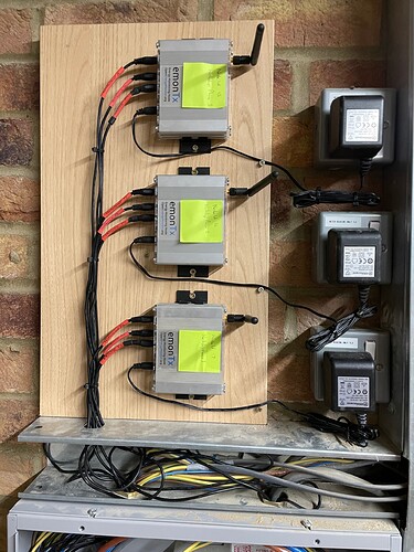
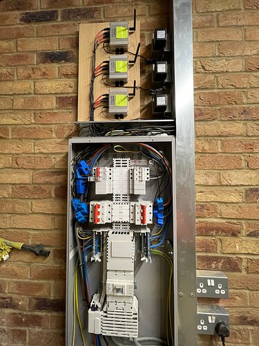
I have 1 emonPi and 2 emonTX, which enables me to track voltage on all three phases (GPO sockets in the panel), the three grid inputs, the three inputs coming from the PV, and the three cables going out to the heat pump.

They are all using the standard builds and firmware, and once the logic of getting inputs to the correct feeds is worked through, it is able to track everything I need. The EmonPi takes the emon TX feeds, and transfers all data up to an EmonCMS server.

(now to work on the other heat pump attributes, other than power usage… :slight_smile: )

Cheers,
Brian

I have pretty much the same requirement here. I went with the 3x Tx solution, one per phase, each running off their own power supply with a dedicated (and labelled) socket per phase.

Currently they are running using radio to transmit to the pi, but it has been problematic a number of times because of radio clashes. I’ve purchased usb serial adapters to replace the radio, just need to program the USB adapters to ensure they remain consistently connected to the same serial port on reboot.


I’m guessing you mean program the device (e.g. Raspberry Pi) so it always enumerates the USB adapters to the same serial port. If that’s the case, you may want to have a look at this thread:

BTW, nice clean installation you’ve got there.

Hi Bill,

Yes you’re right, I meant program the Pi. Thanks for the link to your thread, I came across it previously which lead me to buy the FTDI serial adapters. But like most things I mean to do, I buy bits and then they sit in the box for months before I get around to actually doing it!

Thanks for the comment on the install, and thanks for all your advice on these forums! Without this forum I wouldn’t have got as far as I have so far.

Cheers

2 Likes

Thanks to all those who have responded to my initial post: I understand much better now what can be achieved, and I’ll shortly be in a position to make an order. I’ve run what I’ve learnt by the Italian electrician who originally did the PV installation ten years ago (so he knows where the bodies are buried), and he is actually keen for me to make an order so that he can do the electrical part of the installation, because he likes the look of such a non-invasive solution, which he could propose to other clients – the hardware he’s used until now involves running extra new cables to the PV inverter. The emonPi/Linux configuration part will be down to me (I’m not sure how much of that he’d be au fait with), but I’m on much safer ground myself there. If he’s keen for me to proceed, then I’m keen to try and make what he’d need to do in the future for any other clients as simple and ‘standard’ as possible, and I’d offer to informally ‘consult’ if appropriate, based on my experience of my own future installation.

My house and PV system are three-phase, though. From the responses to the thread, it seems like I might have two main options, with pros and cons for each. I’d be grateful for any comments (or corrections) on my analysis of my best options below:

  1. The full emonPi PV monitoring package, which comes with two CT sensors, for one phase, plus two emonTX units, with four more CT sensors, for the other two phases. This is based on what garnhedryn (Brian Davis) contributed. Four new power sockets would need to be installed, at least one per phase, with the emonPi requiring two sockets.

  2. An emonBase, with three emonTX units, and six CT sensors, two per unit. This is based on what gadgetbazza (Barry Tresadern) contributed. Three new power sockets would be needed, one per phase (if the emonBase were installed a few metres away in the house).

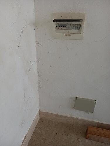
The photo below shows where one of these installation options would go, following confirmation by the Italian electrician. This is a corner of my property, a covered entrance area with the road (and electricity meter) on the other side of the wall on the left, and a neighbour’s property behind the wall on the right. This is where the electricity supply from the grid enters my property (the cables run above ground between concrete poles, along the road, and a line comes down to the meter). This covered entrance is effectively a room, open to the elements at one end, where a set of stairs then leads down to the veranda, from where you enter the house (which is set below road level, the property being on a slope). But this is Sicily, so there is no frost risk, and the location, covered but outside of the house itself, should be ok. I imagine the emon kit, and the sockets they were plugged into, would be contained within a suitable box installed on the wall near the two boxes shown.

The top box in the photo is the first entry point from the meter on the road, and has some surge protection. The lower box contains the six cables I would need to put the CT sensors on: those for the three phases coming from the grid, and also those for the three phases coming from the PV system and inverter about 80m away at the bottom of the garden (this now having been confirmed by the electrician). As Robert Wall pointed out, this lower box thus effectively constitutes the ‘Fuse box / consumer unit’ in the ‘Type 2’ diagram at the beginning of the Solar PV section of the guide. Presumably from here, cables are ducted into the house, initially to the board of circuit breakers, and this is the decision point where energy generated by my PV system is either diverted into the house for consumption, or exported to the grid (with the meter on the road functioning as an export meter, as well as recording consumption).

So the emon installation would go here. To look at the pros and cons of the alternatives:

  1. emonPi and two emonTX units.

Three units, rather than four in the alternative – but the cost is probably similar for either. The emonPi would need to be installed here on the wall (and not in the house), but the electrician says he would duct an ethernet cable from there through the house to my internet router (although I have experimented with a wifi extender to this point, which seemed to work ok). The emonPi and the two emonTX units are next to each other for radio traffic, and the danger of radio collisions is presumably reduced by having only two emonTX units rather than three. The emonPi can only have two CT sensors (which is all that I need), but there is no expansion built in, as there would be with three emonTX units (each of which can have four CT sensors). If I understand correctly, I would be able to keep the standard sketch with this configuration, whereas I would need to intervene to switch to the three-phase sketch with the three-emonTX alternative. Similarly, I can order the two emonTX units to be configured with two node IDs at time of purchase (set by a dip switch), whereas if I order three, then I have to invoke a procedure myself to reconfigure one of them to a third node ID. These last two points have to do with the ‘out-of-the-box’/’keep it simple’ idea I mentioned earlier.

If instead I go with a three-emonTX solution, then I have available four CT sensors per phase, and I can keep the emonBase inside the house if I wanted (about 12m away from the wall location, with line-of-sight through a wooden door). I imagine the location of the emonPi/emonBase inside or outside of the house is probably not too important, as long as it can communicate easily with the internet router, and I would in any case be viewing the emonCMS data on another computer via something like VNC.

However, I am concerned by the potential radio clashes between the three emonTX units and the emonBase that others have written of. I would prefer to stick with the default radio solution if possible, in part because it’s more ‘out-of-the-box’, but also because alternatives (such as the ESP8266 wifi module) involve more power consumption, meaning the AC-AC adaptor for each emonTX to measure voltage for that phase can’t also handle this extra power requirement, and the 5V USB power supply must be used too, doubling up on the power sockets I would need to have installed. So, to keep it simple, I’d ideally like to use the default radio option. However, I’m making the assumption that two emonTX units communicating with an adjacent emonPi via radio does not involve much of a risk of collisions, whereas three emonTX units communicating via radio with an emonBase maybe a few metres away may instead be problematic, as it evidently has been for some people. Is that a reasonable assumption?

Based on the above considerations, I’m currently leaning more to the ‘emonPi + 2 x emonTX’ option rather than the ‘emonBase + 3 x emonTX’ alternative, because of the reduced risk of radio collisions and because I might need to intervene less on the ‘out-of-the-box’ configurations (no need to intervene to change sketch, or change node ID).

I’d be grateful for any comments, advice, or corrections to my reasoning as expressed above. I’m ready to order, and keen to get started, but don’t want to have made any show-stopping mistakes – my background is not technical.

The last thing that is worrying me is Italian customs, post-Brexit. I recently turned 70, and arranged online to have my new driving licence delivered to my UK address, intending to pick it up during a (subsequently cancelled) Christmas visit. My brother picked it up and sent it on to me, inside an apparently oversized birthday card for me, using Post Office Track-and-Trace. This shows it entered Italian customs on 24th January – and there’s been no change to its status since then. From what I can make out, using Track-and-Trace designates what’s being sent as a parcel, which now means it has to go through customs. If a birthday card can get lost in Italian customs for nearly three weeks, what’s likely to happen to the hardware for a (small) energy monitoring solution?

The Shelly 3EM suggested by Zoltan would not have this issue (Shelly apparently distributes in Italy), and is intended for three-phase, but this certainly doesn’t look ‘out-of-the-box’, I can see it isn’t ‘open’, and I would need too much support in things I don’t know about. I need to learn to walk before I can try to run. Regarding Italian customs, I can but hope… my now-belated birthday card (and driving licence) would be a start.

The emonBase needs a power supply, the phase is unimportant.

No, if you have one emonTx per phase (or an emonPi on one phase) all use the standard single-phase sketch.

FTFY

Not necessarily. With care, the emonTx’s with the ESP8266 could all be powered by a single 5 V USB adapter, but you’d need a higher output current than the standard 1.2 A one from The Shop - about 3 A should be plenty.
But - if you’re running an Ethernet cable anyway, maybe an Ethernet switch and 3 Serial-to-Ethernet adapters instead of the Wi-Fi ESP8266? And just to confuse matters further, you could do EmonPi + 2 emonTx’s with serial-to-Ethernet adapters and an Ethernet switch, or even (I think) serial to USB adapters on the emonTx’s straight into the emonPi. But these involve a bit of hardware and software fiddling, so that is a consideration, from what you’ve written.

It is. Although the modern software tries to avoid collisions - and largely it succeeds - there’s no guarantee. The receiver, whether the emonBase or the emonPi, plays no part in the blocking process. It’s only the number of transmitters.

One point in passing: Each emonTx gives you 2 spare current channels, but until you have a load directly connected to that box outside, you can’t realistically use them for anything. If you might have an EV charger out there, then that’s a consideration.

If you are affraid of the integration of a Shelly, maybe someone can explain you, what you have to do to have a 3-phase Type 2 solar configuration in emonCMS.
For a single phase system there is an automatic configuration available. This you could do probably 3 times for your system.
But to have the information you see on your meter on the road, you would have to do some configuration by yourself.

The other question is, what measurements are you really interested is?
You say you have information about solar production from your inverter.
With a single Shelly you could see what your meter on the street sees, per phase and 3-phase summed up.

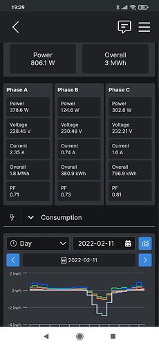
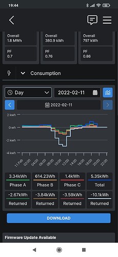
Here is a screenshot from the Android app, that you get out of the box without any configuration.
It shows current values and imported/returned energy per day/week/month/custom period.
You can also download your data as a .csv file, that can be imported to Excel for further analysis.

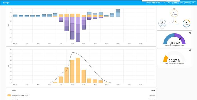
Here is what Home Assistant Energy dashboard displays from my Shelly and data read out from the Solaredge Inverter. It would also work with 2 Shellies.
This one is really easily configured, unless you try to get some more automation done.

You sould need a new fuse for your 3-4 sockets anyway, it is also needed for the Shelly.
If you let install it in a box that is big enough to accomodate the emon solutions afterwards, you have a way out.

(I am not affiliated with Shelly but having considered myself the OpenEnergyMonitor solutions, I found that it is not a big friend of 3-phase systems. But emonCMS to use as a logger and display/analyzer is working great.)