Recently started my ASHP journey. Been learning a lot here, but I am still not where I would like to be.
My main goal is system longevity, then comfort/energy usage balance
Let’s start with system specs:
Ecodan R32 PUD-SWM80YAA + cylinder unit EHST20D-YM9D (FTC6)
100l 4 pipe buffer tank (vertical inlets/outlets)
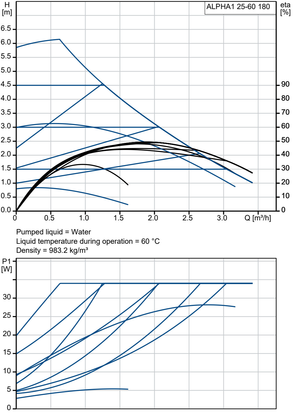
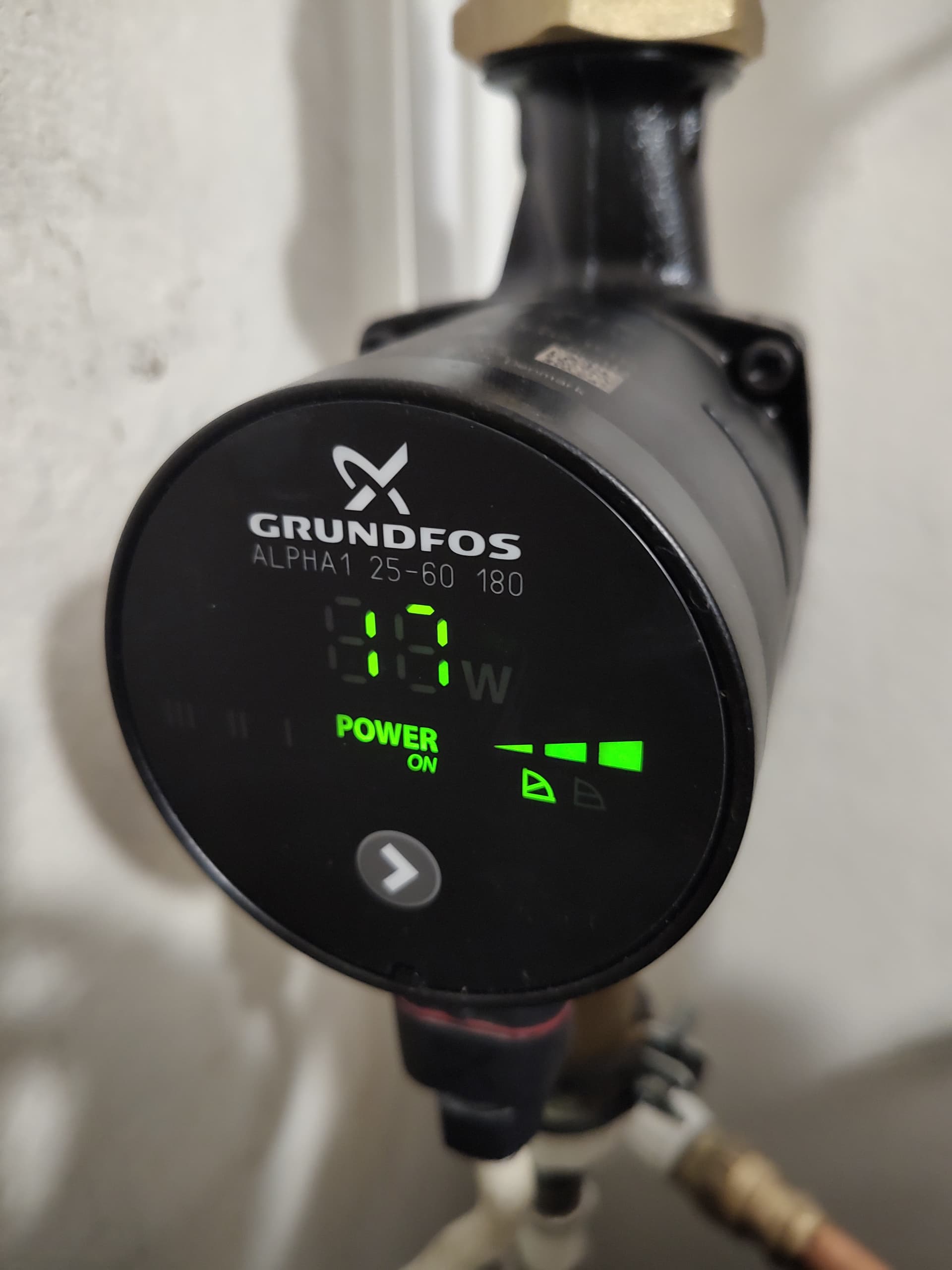
Grundfos Alpha1 25-60 180 secondary pump on the return side of the radiator loop
single zone radiators, with estimated total radiator output of 3.2kW with target room temp 23C, dt 5, ~10l/m (numbers from John Cantor’s calculator)
poorly insulated (mostly leaky windows) house in Finland
And settings:
running in AA mode (room sensor in the middle of the house), with target set to 23C
FTC set to 30/45 min/max flow temps, +5/-9 upper/lower temp diff, room temp normal mode 10 minutes
internal pump speed 3 (~12l/m), external set to level where temp diff between buffer tank in and out hot/cold pipes is about the same (I don’t have a flow meter for the external pump, and I cannot understand the flow characteristics from the official specs)
rads with smart TRVs. 100% open until ~24C, after which they start closing gradually. 2 bedroom TRVs start closing gradually at ~23C
My problem now is that I cannot get the heat pump to run constantly (or run in very long cycles). It seems like it only starts modulating at temps close to 0, but that sounds a bit odd to me.
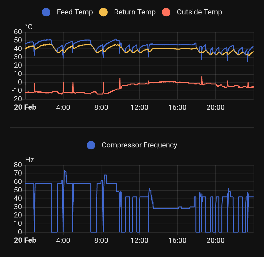
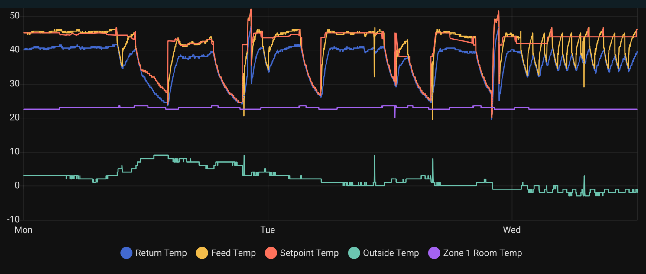
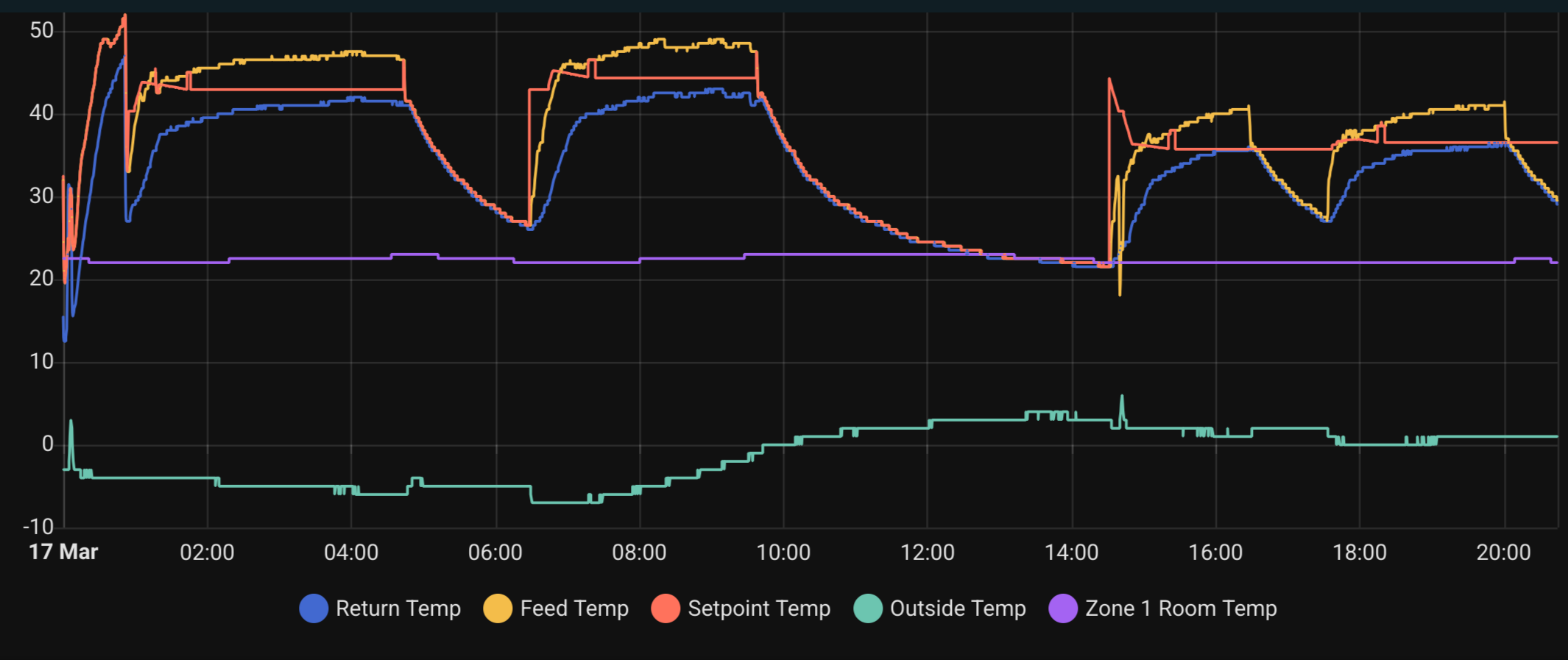
Here is a graph from yesterday (the max flow dt is about 5, in case scale is not high res enough)
Actually, I remembered that yesterday it did reach the room setpoint temp (23), at around 16:20, and then turned off at around 18:10, followed by a defrost. After that, I lowered the max flow temp from 45 to 42
I haven’t touched it today, and it is doing a similar thing
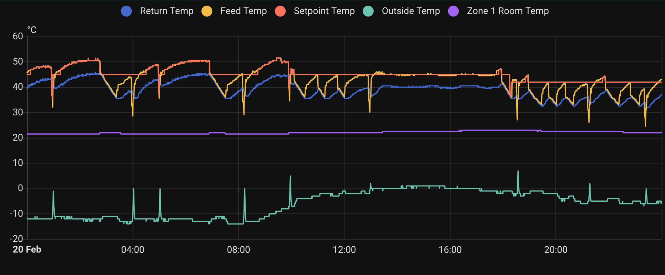
Sub zero during the night, reached 0C after 8 and did a nice long run after that. At 14 it ran a defrost, at 17, I closed all the rads for a minute to see if it would go back to the long cycle (and it did), and at 22 is the DHW schedule. Never reached the room setpoint
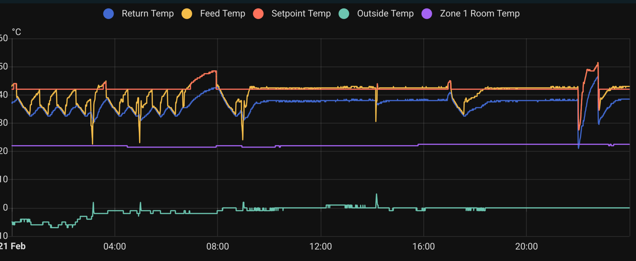
Milder day, basically no sub zero temps. It reached room setpoint at 13, 15, and 19:30. Don’t know what those other dips are at 5 and 9, but not worried about those few cycles per day. 22 is again DHW schedule
I have left it alone since last message, and it has not run continuously for more than a couple of hours. Since it then also stays off for 30m-1h in between cycles, I am not concerned. Outside temps have been at or slightly above 0.
However, today, it did the first continuous long run (8h) since the 22nd. It was also the first time I have seen the compressor frequency stabilise below 26Hz (~3kW), at 16Hz (~2kW). When trying to understand the reason for this, I noticed that the outside temperature has been stable at 5C or slightly above during that period. Outside temp has not been this high since the system was installed.
This now leads me to believe that the FTC has some logic that dictates the minimum frequency/output power at any given outside temperature.
It sounds a lot like something that could be the product of the WC curve, but that doesn’t explain why it only modulates and stabilises at certain temperatures. Iirc, the curve was set linearly to -15:45, 0:40, 25:33 (outside:flow), but running on AA, so it does whatever it wants with the target flow temp anyway.
I don’t remember reading anything about minimum output power based on outside temp, but does it make sense, or am I missing something obvious?
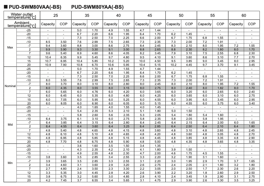
your radiator output is quite close to the min output of the heatpump.
outside temp: 2, feed temp: 35c, min output: 3.1kW
outside temp: -2, feed temp: 35c, min output: 3.5kW
outside temp: 2, feed temp: 40c, min output: 2.9kW
outside temp: -2, feed temp: 40c, min output: 3.3kW
If the buffer tank cannot take this min output it will cycle.
did you check the output and input of the primary and secondary circuit are in balance? or At least the secondary circuit should pull more. (calculate it with output kW = flow(L/m) / 60 * (feed - return temp) * 4.2 for primary and secondary circuit)
Is your thermostat generating demand during the pause ? Cause 30 mins pauzes doesn’t sound like typical cycling due to min output. It could be that your thermostat is doing some PWM. Your compressor frequency is also not near the min
Thanks for the reply, and for your work on esphome-ecodan-hp (it’s what I’m using to pull the data)
ok, so my assumption was correct. I would like to stay away from modifications like that that could have impact on the warranty. I would hope there was a setting for this, or a way to trick it in software… I know there are firmware updates available, but I am yet to see concrete reports about the before and after behaviours
I have previously looked at that part of the manual, but did not fully understand it. Especially the part where the min output goes down with higher flow temperature. I have lowered the max flow temp from the default of 60 to 45 a long time ago, (as it seems to be widely accepted that lower flow temps = higher efficiency) and also to not get the rads so hot. I am considering increasing it now, but it is hard to achieve conclusive results because of all the hidden logic of the FTC
I’m going to guess that with primary and secondary circuits you mean the water circuit of the heat pump and the radiator circuit, and not the refrigerant and water circuits of the heat pump. I currently have no way to measure the flow speed of the rad circuit, so how I’ve done it was to lower the speed of the ecodan pump, so that the temp difference between both feed and return pairs of the buffer thank is about the same. (I put painters tape on top of the pipes and measured them with an infrared thermometer from the same distance)
the only thermostat in use is the stock ecodan room wireless sensor. When outside temp is below 0, I suppose it is generating demand, since most of the day it never reaches set room temp (and AA setpoint remains high). The problem now is pretty clear to me: with lower outside temps, min compressor frequency/output is higher than the rad output, meaning that flow temp will rise quickly and cycle often, which also makes it so that it takes longer to warm up the house. When outside temp allows for ecodan to operate at lower output, it happily runs for a long time
I think they easiest way of looking at it is to consider COP for a given feed temp. The higher the feed temp, the worse the COP gets (It cost more energy to raise to higher temps). Because output power = COP * input power, we can roughly see that the output power reduces when the COP reduces (and we can reduce the COP by increasing the feed temp)
You already lowered the pump speed on the ecodan, this means that the primary circuit was adding more heat than the secondary could absorb and eventually your buffer tank will be ‘full’ and the heatpump will stop. On ecodan-esphome-hp the output of the primary circuit is calculated via the sensor: sensor.ecodan_heatpump_estimated_output_power
Possible solutions for your issue:
increase pump speed of secondary circuit
increase capacity of the secondary circuit if possible (open more radiators, add more radiators, add ventilators)
lower pump speed on the ecodan
increase feed temp
3 lowers the output on the ecodan and 1+2 increases the input on the secondary circuit.
4 is trying to avoid falling under min output of the ecodan, but the secondary circuit needs to be able to absorb it because we are increasing the output this way.
But it does seem that this heatpump is a bit oversized for your install, and that’s hard to get it work properly.
btw: are you sure its not defrosts your are seeing on Wednesday ? you can plot the defrost state on top to see. Looking at the graph I see only one defrost, but that could be due to scale
Ok, thanks for the explanation. I think I get it a bit better now. There are many variables and lots of conflicting information out there, so this is a bit hard to navigate.
Yes, I know about the estimated output power sensor, but I find it easier to visualise the modulation from the compressor frequency sensor.
I have lowered the Ecodan pump and increased the rad pump a while ago, because I read that the cycling issue was being caused by the mixing inside the buffer thank. Now I am starting to realise that to achieve less cycling, the mixing is necessary. It seems to be a trade between efficiency and cycling, and I will gladly pay a bit more in electricity, if it means that the system will last a bit longer.
From the manual, it seems like the lowest acceptable flow rate for this heat pump is 9l/m. Level 3 on Ecodan is being reported as 11l/m, so I might not be able to go lower without some issues, but I’ll try level 2. I will also increase the rad pump speed a bit.
All rads are usually open (lockshield/balancing valves are 100% open), and the TRVs only start closing gradually about 1 degree above the room set temp (22.5). Bedrooms start closing a bit before, but I do not see a significant impact in cycling even when both are fully closed. I will consider rad modifications if I get nowhere.
It is possible it is oversized, though the instalation was done by a reputable company in the area. I would hope they know what they are doing.
Your observation is correct, there has only been one defrost today, 2 yesterday, and 1 on Monday.
Issue is also that around 2c ambient the min output remains around 3.0-3.6 kW
It goes to 2.7 kW for 55c feedtemp. So only realistic options is to increase input for secondary circuit. You should keep all radiators open, don’t close (even a bit).
What are the delta T for primary and secondary circuits?
What you could try is to heat in interval. Say 3 hours heating at a certain feed temp and pause for an hour or so. If its possible leave the secondary pump running during this pause.
I have to close the bedrooms a little bit eventually, because they are at the start of the circuit, and they would get extremely hot before the rest of the house has a chance to reach temperature. Either that or reduce the flow in the lockshields, which has basically the same result afaik.
Just measured (have not messed with pump speeds yet today):
Primary out: 41.9
Secondary in: 38.8
Secondary out: 34.0
Primary in: 35.7
So, that’s 6.2 on primary and 4.8 on secondary. Average temp indoor 22.7, outside -2
If I understand this correctly, it means that the secondary pump is currently running at a higher flow rate than primary.
I guess heating in intervals is one option. The secondary pump is “dumb” and is not connected to Ecodan in any way. I suppose you mean using server control and some automation from HA. I’m not a fan of having critical things depending on smart home though…
Pump has 3 different modes (constant flow, relative pressure, constant pressure), with 3 levels each. The only data I can find is this, which doesn’t mean much to me:
On the other hand, I think I still need to be convinced on the effects of flow rate and flow temperature when it comes to cycling. Over the last couple of months, I have tried:
primary flow rate higher than secondary
secondary flow rate higher than primary (educated guess)
primary and secondary flow rates balanced (guess based on temp diffs)
lower base flow temps on WC curve
lowering max flow temp (to about 40)
increasing max flow temp to 55
WC or AA
lowering room set point temp by 2 degrees
… and none seems to have any conclusive effect on the cycling.
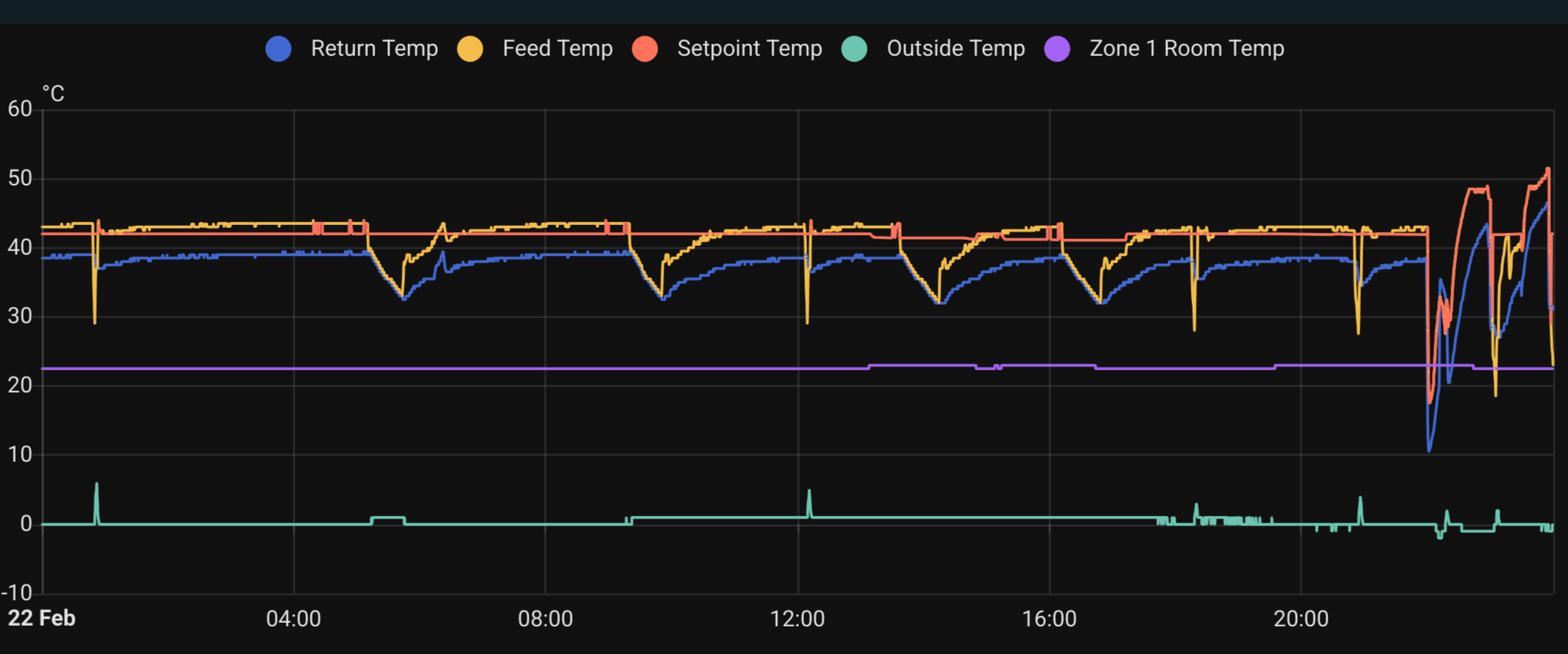
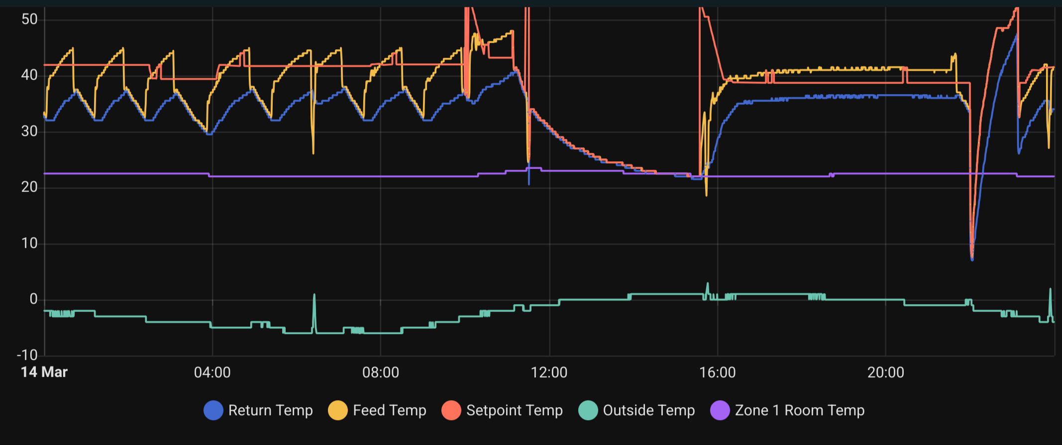
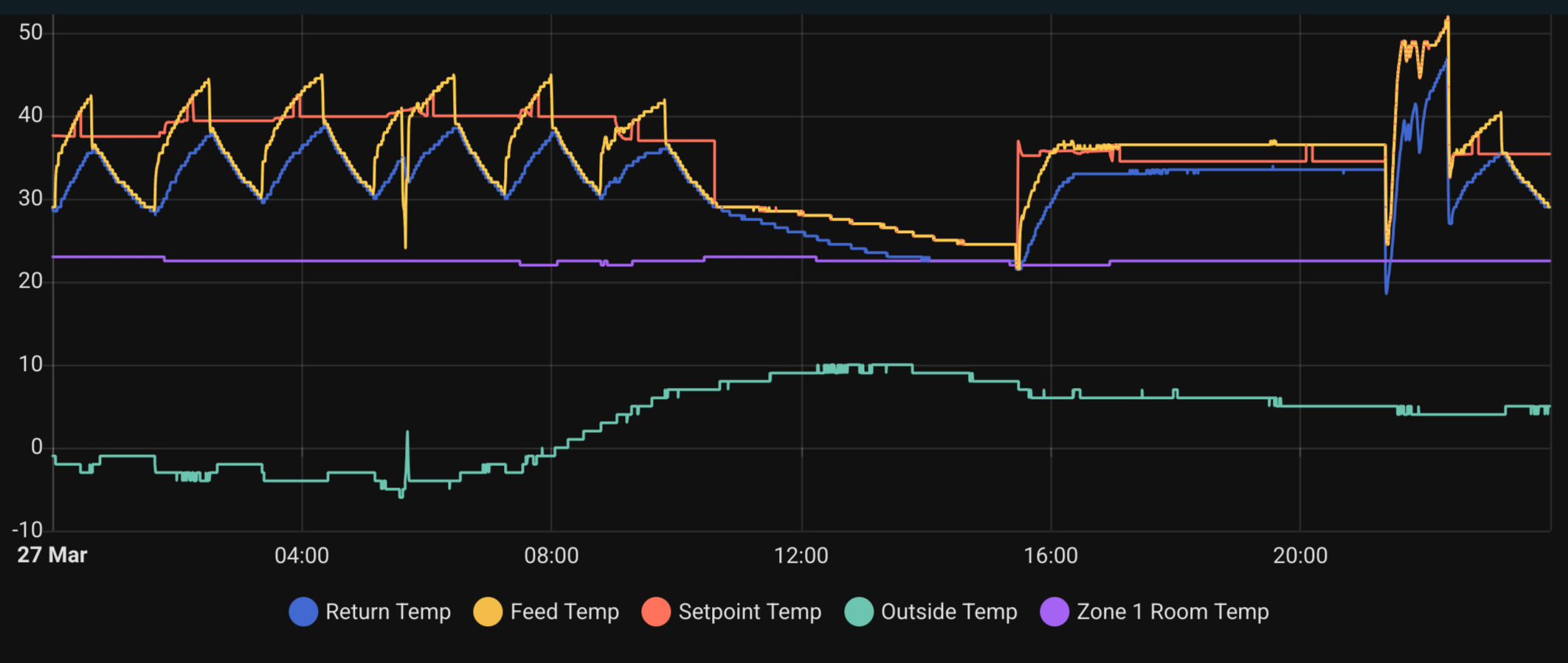
Then, 2 days ago, I updated the FTC from 1801 to 2001. I don’t want to jinx it, but it looks much better. Here is before and after from days with similar outdoor conditions (ignore 22-01 window, that’s DHW)
Another thing that does not help my doubts above, is the fact that for the periods above, the frequency/output power is about the same in the respective windows. In other words, if the cycling happens because my system cannot handle 5kW output, then it should have either continued cycling or flow temps would rise higher… Right?
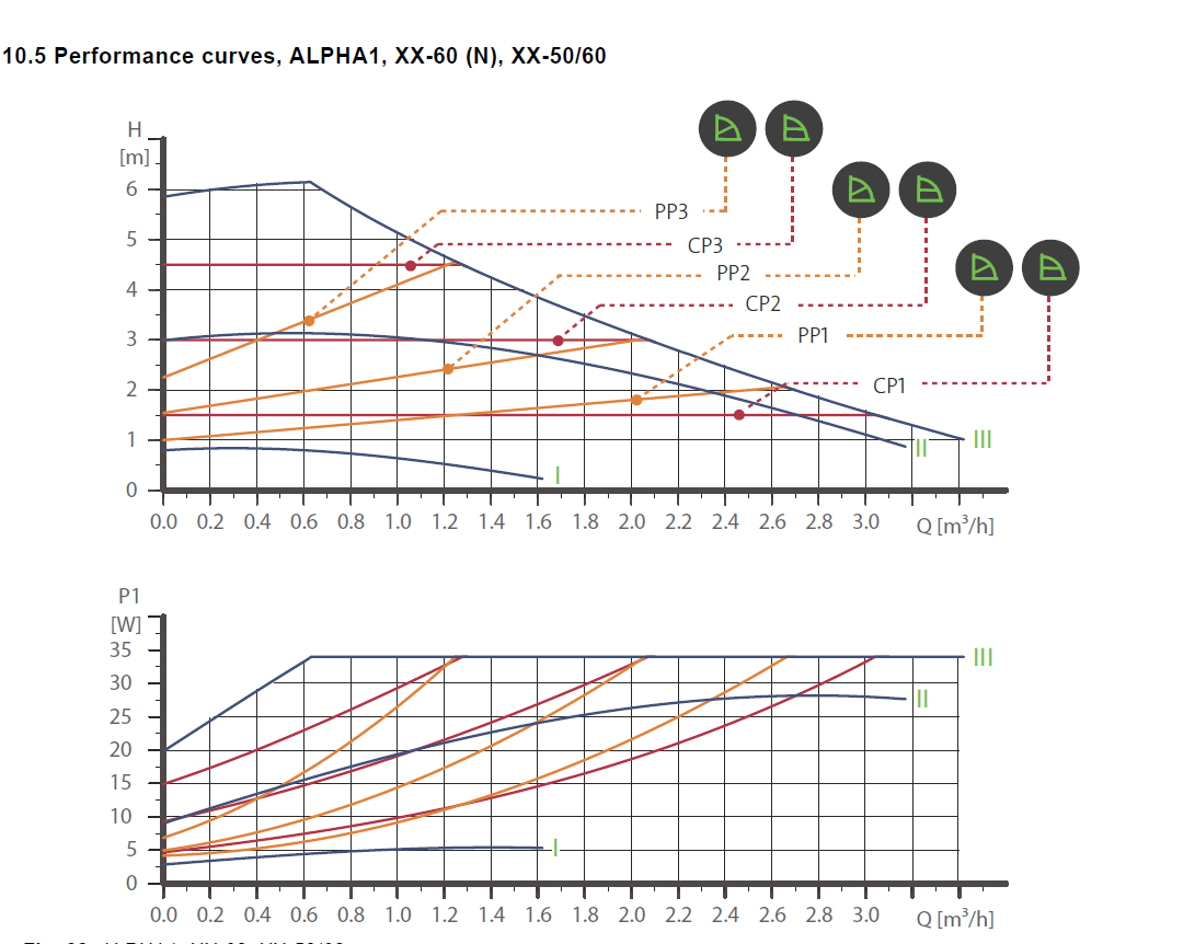
Re that Alpha1 pump above, if it shows the power in watts then the flowrate can be derived easily enough from the pump curves, if it does (show the power) and if you are interested, post a close up view of the pump front showing LEDs etc and I should be able to derive the flowrate from that data.
OK, that looks like its on (proporional pressure) PP3, at 17W should be circulating 0.65m3/hr @ 3.3M (head). If you wish to increase the flowrate, you have two choices, one, is to press the setting button for ~ 5 secs, the pump curve “picture” will then either move to the right to show the same type of picure but with a straight line which is (constant pressure) CP mode, you then press the setting button briefly until the 3 LEDs are illuminated, this then should be CP3 which should give a flow of ~ 0.76m3/hr @ 4.5M & ~ 26W. If a still higher flow is required keep the setting button pressed until the three LEDs on the left of the pump are illuminated, this is fixed speed, constant curve, CC mode, keep pressing the setting button briefly untl the three LEDs on the left are illuminated, this is the max, CC3, pump
setting and should result in a flow of ~ 0.94m3/hr @ 5.4M & 34W.
Aloso, IMO, balancing should not be attempted in PP mode because the pump speed and head will decrease when you throttle in any lockshield valve, and increase if a lockshield is opened up, I would use CP mode.
Thank you for the explanation. I have changed it now to CP3, and it is reporting 27W. If I got this right, it should be somewhere between 0.85-0.9m³/h (~14-15l/m).
The Ecodan/primary pump on level 2 is reporting on average 12l/m. So, on PP3, secondary is ~1.5l/m slower, and on CP3, it is ~2.5l/m faster.
I have tried CC3 in the past, when I was trying the extremes to see the impact, but it is unusable anyway in my current system due to the noise. The plumbing is 20mm OD composite (16mm ID), so it is probably the limiting factor at that point.
Anyway, I will leave it like this and monitor for a few days
You need to take the feed/return temp in consideration when tweaking the pump speed. Monitor feed/return temp of both circuits and then tweak the pumps for capacity.
Regarding oversized: Maybe that’s not the correct term, but your heatpump does not seem to be able to module back to a level that your radiator capacity is able to consume. Lower capacity units can normally modulate to lower output. You need a unit that can module back more (generally a lower capacity unit). Apparently on the 17th, you had a situation where the secondary circuit was able to take the produced heat output.
Could it be that the buffer tank was cooled down a lot, or you might had some open windows?
Your heatpump will continue to run when the condition below is not violated:
Produced heat (min output) from the primary circuit has to be <= capacity to absorb this heat
are you able to plot the feed/return temp from the secondary circuit ?