I’m in a new build property, 220m2, single floor. We’ve had an Ecodan 11.2kw installed. We’re running two zones, one ufh, and the other is radiators in the bedrooms.
My issue is that when the radiator zone calls for heat it does not seem same to cope with the minimum output of the ashp. This is even after removing all TRVs and running the rad circuit open. For example, if the set flow temp is 35, it’ll just keep creeping up until it hits over 40 and shuts down. At this point the circulation pump also stops so the radiators just become cold. The ashp will then not start up again until the flow temp reading drops to low 30s again. This takes 30 to 40 mins! Surely this can’t be right?
The only solution I’ve found is to have the flow temp set at around 45. This means the rads get hot and stay hot, albeit with a terrible dT of 1 degree!
It’s obviously not ideal though as not very efficient but also those temps result in my ufh circuit becoming very hot. A quick check today showed the floors sitting around 26 degrees which is pretty close to the max allowed.
If at least one ufh room is on at the same time as the radiators then the system functions fine.
Is there anything I can do here to make it run better?
if you set to auto adaptive you can set a max overshoot temp where it will stop ( I think this is max 4 degC over flow temp) and a restart temp ( upto 9 deg C below flow temp) when it will restart. The pump continues to run while it is cooling down. The flow temp is taken from you WC curve but adjusted up when room temp is below target and down when room temp above target. The room temp is measured at the controller so this does depend on it been in a good spot which is why I installed the wireless remote one.
The minimum output of the 11.2kW Ecodan at a flow temperature of 35C is 4kW, while at 45C is it around 3.5kW. So it seems your radiators can just about dissipate 3.5kW but not 4kW. And by the way, a dT of one isn’t terrible, at these mild temperatures your dT will/should be low and less than 5.
You mention that if one UFH zone/room is on then all is fine, that UFH zone provides the extra 0.5kW of heat dissipation needed to avoid the system from cycling off. Would it be possible to keep one or more UFH zones/rooms always on/open? Also, are you aware that usually the best (and most economic) way to run a heat pump is to use a minimum number of zones and ideally just one?
I’ve not tried auto adapt as it was my understanding it doesn’t work when there’s two zones?
Unfortunately when building the house I didn’t look too much into the heating side. I thought I’d leave that to the installers as I thought they would know better. I now wish I had known what I know now and gone ufh throughout with just one zone.
Unfortunately the way they installed everything is a thermostat in every room. TRVs on the radiators. I’ve since removed those as obviously they were making the issue worse.
I’ve thought about trying to run the whole house as one zone, easy enough to remove the actuators of the ufh manifold, but not sure how I would make both zones call for heat at the same time. Each zone has its own circulation pump.
Installer was wanting to put a buffer in at one point but I want keen on that. Then suggested a volumiser on the radiator circuit. But surely that would just delay the problem for a few minutes?
Could you expand a bit more on how your system is piped and how the controls are wired please?
You have the primary circulation pump controlled by the Ecodan and then two further secondary circulation pumps (one for the radiators and another for the underfloor) - is that right?
What is it that decides when the secondary circulation pumps run - is that the thermostats in each room? How are those thermostats connected to the heat pump controller?
With multiple secondary circulation pumps you’d typically have a buffer tank or low-loss-header to provide ‘hydraulic separation’ between the circuits. If you don’t have a buffer, how are the pipes for the underfloor and radiator circuits connected to the flow and return from the heat pump? Are they just connected via tee fittings?
I have a broadly similar set-up, with radiators on one zone (with one secondary circulation pump) and an underfloor manifold on another zone (with a further secondary circulation pump) - but I have a low-loss-header to decouple those circuits from the heat pump flow and return. I leave the secondary pumps constantly circulating water around the radiators and underfloor (effectively those are always ‘calling for heat’) and it’s the heat pump’s weather compensation algorithm which decides how warm that water needs to be.
You have the primary circulation pump controlled by the Ecodan and then two further secondary circulation pumps (one for the radiators and another for the underfloor) - is that right?
Yes that’s correct.
What is it that decides when the secondary circulation pumps run - is that the thermostats in each room? How are those thermostats connected to the heat pump controller?
Yes, any of the thermostats in the radiator rooms sends a signal for heat which triggers a relay switch. This will cause the main pump and radiator circulation pump to fire up.
For the UFH rooms there’s a heatmiser wiring centre which controls that side. Same as above, call for heat will fire up the main pump and ufh circulation pump.
And of course both zones calling for heat at the same time has all the pumps running.
With multiple secondary circulation pumps you’d typically have a buffer tank or low-loss-header to provide ‘hydraulic separation’ between the circuits. If you don’t have a buffer, how are the pipes for the underfloor and radiator circuits connected to the flow and return from the heat pump? Are they just connected via tee fittings?
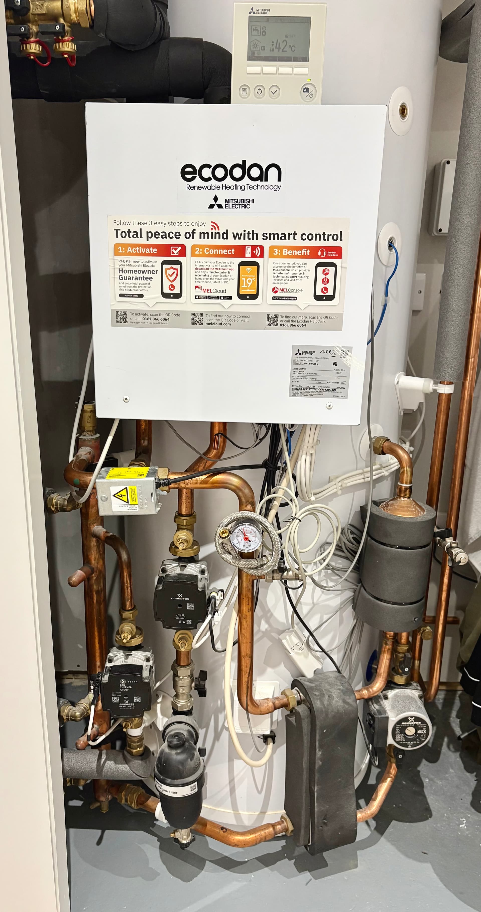
I’ve attached a picture of my setup. Main pump in the middle, radiator circulation below it. Ufh pump is hidden behind the wall on the left. I assume that’s a low loss header at the bottom of the setup?
It looks like you have a “simple” 2 zone design, where you run a single flow temperature in both zones (You are set to fixed flow of 42C by the looks of your controller)
There is a sort of LLH, the circulation pumps for Zone 1 or Zone 2 will cut in & out as there is demand for the zone but i find it’s not perfect.
You set the flow temperature for Zone 1 (not sure if this is your UFH or Rads)
In a complex 2 zone, you have a mixing tank and mixing valve which would provide the two zones to operate at independent flow temperatures.
Yeah, that sounds right. I just set the only flow temp and it is the same for both zones. Zone one being radiators.
I had it on WC before but changed it to fixed flow for now so I can get heat to the radiators without it cutting off. 42 seems to be the lowest temp where the rads can dissipate the heat.
The tall fat vertical pipe on the far left is the LLH. The topmost and bottommost connections is the primary flow from and to the heat pump (except when heating hot water), and the two smaller connections at the top go to the two central heating circuits via the pump left of the primary pump, with a second pump behind the wall.
I agree with Tim that’s a Low-Loss Header on the left of the photo, connected as he explained. That will provide a degree of ‘hydraulic separation’ and let each of the circulation pumps do its own thing (which is good).
So presumably that’s a plate heat exchanger at the bottom, to the left of a fourth circulation pump on the DHW circuit (not related to your original question but I’m just curious).
It supports 2 zones (simple/complex setups). You will be able to set min/max flow temp per zone. But Ideally you need to have the ufh zone open. It has anti cycle protection where it boost the feed temp for you (if enabled) to avoid the cycle due to min output. It extend the run a bit, until you hit max flow temp or setpoint reached.
So is there a way to have both circulation pumps come on when a thermostat from either zone calls for heat? As the radiator circuit is just too small and I get the problems I mentioned above. I would much rather just run it all as one zone so I could run in WC mode.
That’s what happens for the main (primary) circulation pump already, so perhaps you could change how the radiator and underfloor (secondary) circulation pumps are wired so they all switch on together?
I looked through the FTC installation manual for a way to combine both zones; I thought there’d be a dip switch or setting but I can’t find one. There are some ideas to try in this thread:
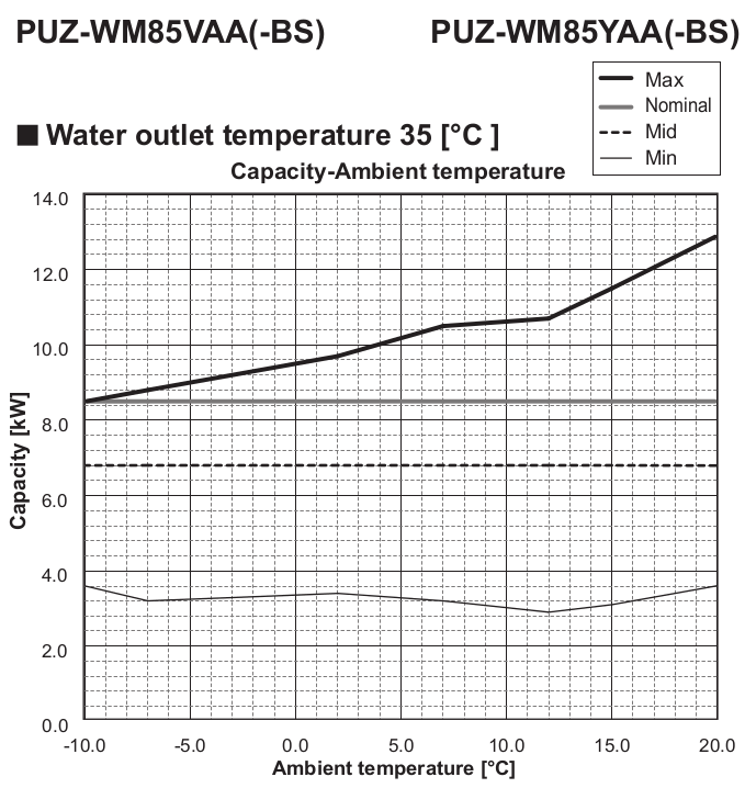
I was talking to the installers. They’re thinking of switching out the 11.2kw unit for an 8.5kw and keeping the two zones separate. One ufh and one rads. Does anyone know be minimum output of the 8.5 model? My only worry would be if there’s enough output for the coldest of days.
This shows the minimum to be around 3.5 kW, but it can reach or exceed 8.5 kW at all temperatures. For comparison, your current unit can do between 4 and 12 kW.
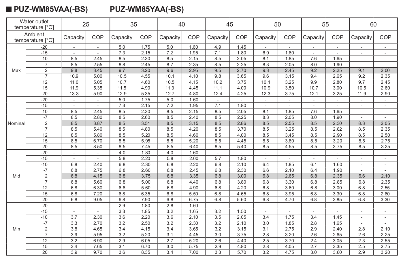
Here’s that same data in table form for a range of flow temperatures: