Are they supplied with a flylead or are they CT’s that you need to add wiring too? If it’s the latter you would be better off putting the TVS or Zeners at the CT to protect in the event of wiring breaks or the jack coming off etc.
same phase for AC-AC readings, CT are on their own phase tho…
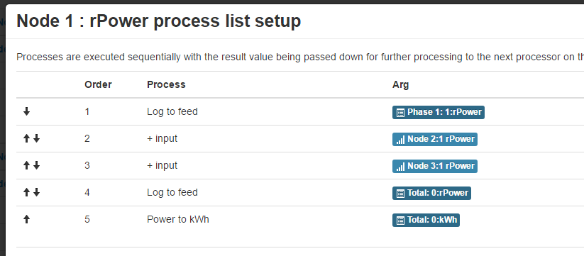
It kept making the feeds page not load… i saw it was creating 2 feed records into the MySQL db every time i tried to make one new feed and it returned an “unknown” error. it felt like they were out of sync… tho I do not entirely understand how REDIS is used…
Ahh i see, i thought that’s what it did, so… thats out the window… i was only asking cause the charts look very ermm not smooth ![]()
ill paste some screens!
I’m still not sure here, are you saying all 3 emonTx’s currently have thier AC:AC adapters connected to the same phase but the CT’s are on the separate 3 phases? That would most likely make more sense of understanding the power factors.
You’ll have to show us when it happens again.
here is latest readings
yes this is currently the case, just testing they all actually worked of course… and still waiting on the installation of the separate socket phases.
I shall enable REDIS again on the config and see what happens… and if it breaks then ill try get more info for you ![]()
But if you put all the CT’s on the same phase as the AC:AC adapters you could compare them, side by side and confirm they are all working “similarly” rather than “just working” but potentially very different.
very true ![]() ON MY WAY! lol
ON MY WAY! lol
5 posts were split to a new topic: Enabling Redis is causing issues in emonCMS
ermm… so CT2 is negative cause its flipped if im not wrong but has a similar PF if we dont count the negative value…
CT3 i have no idea… 
EDIT: ohh wait that has no Amp reading… ish
EDIT2 - same AC-AC phase, all CTs into same phase
That looks much better power factor wise, but the other values are very inconsistent so it’s difficult to compare, do you have a steady load you can monitor with the 3 CT’s or can you use emonhub or similar so that all 3 nodes results are simultaneously shown.
Steady load i dont think i have anything lying around tbh…
those are live feeds from the serial output, they should be very simultaneous accounting for my fast screen /dev/ttyUSBX copy paste skills 
but from emonhub i can paste too:
not to worry, The fact they are all running on 10sec intervals and not synced will result in variation anyway.
would sync be a good idea?
and how would that be accomplished if so?
It would be a good idea but it’s not easily accomplished with what we have, emonhub would need to poll for the info or a “trigger signal” would be needed, either way the sketches would also need changing.
For the moment the nearest you could get is to power cycle (not reboot) the Pi so that the 3 emonTx’s all start at the same time, it will go out of sync over time but to be honest with the load you have varying so much and a discreet sampling sketch they would need to be absolutely in sync to be directly comparable, hence the “better to test on a constant load”.
I use a 2Kw heater and a long phase cable to wrap through the CT a couple of times, it will only vary slightly then as the voltage creeps up and down.
Paul, the ones I bought are…
Regards
Dave
That’s the easiest way to test, you can also test at various increments just by adding or removing CT passes.
Looking at those CT’s I’m guessing you will be extending the wires, if it were me I, would factor the diodes in at that point rather than putting them in the jack connector, but I don’t think it’s overly important.
Yeh I was going to twist decent alarm cable together and solder with heatshrink to extend.
I’m hoping these work well as these are a lot smaller than the standard CTs and with 12 CTs in my fuseboard, its cramped to say the least.
Regards
Dave
A CT is the dual of a voltage transformer. If you short-circuit a (normal) voltage transformer, you get excessive current and it burns out. A current transformer does the opposite: If you open-circuit a current transformer, you get excessive voltage (as it tries to drive the current it generates into a near-infinite impedance) and it flashes over and destroys the insulation. So, as I’ve written may times in the past, a CT can always be short-circuited in safety, because then it is delivering zero power.
Therefore, there are two things you can do:
- Short-circuit the CT before you unplug/disconnect it, or
- Fit a pair of voltage suppressors (or one bidirectional one), or a pair of zener diodes in series, to clip the voltage at some safe value.
It’s not likely that a very small CT like the ones we use would kill, but it could easily be very painful, and would certainly destroy any delicate electronics that couldn’t handle the current.
{Sorry I’ve been away for a day - I’m back on-line now.}
I have seen faulty jacks. The plastic insulation between the components is either squeezed out of position (so a short circuit), or it has not been assembled properly and prevented two metal parts that should be touching from giving a good contact.
Thanks Robert, what voltage diodes would you recommend? also you recommend a pair of diodes in series? what benefit do you have using two diodes rather than one?
Regards
Dave
What voltage do you want? Anything that gives negligible leakage above the working peak that you need for the input should be fine. The YHDC used to be 22 V, the latest are lower.
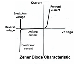
You need two in series because the “reverse” voltage of a zener diode is ≈ 0.7 V, the same as the forward voltage drop of any diode, and you don’t want it clipping at 0.7 V one way and (say) 15 V the other way. (Any diode will show the zener breakdown characteristic in the ‘reverse’ (blocking) direction - but the voltage at which it happens isn’t controlled. So a Zener diode actually works - passes current - in the “reverse” direction compared to an ordinary rectifier diode.)

[from: Semiconductor Primer, semiconductors 101]


