I’ve been looking all over the forums for information regarding the project here and one thing that’s still confusing me is whether the emonTx shield requires and actual arduino or if it can work on its own (with emonBase or emonPi).
I’m trying to monitor a 3 phase system and require (as far as my understanding goes so far) 3 emonTx (one for each phase) along with the other bits, CT, AC-AC adapters and the either a emonBase or emonPi.
On a side note, i see there is an option for longer stack-able headers, can i stack the emonTx shield and then connect them to the emonBase via serial (I’ve seen this mentioned before but was with older v2 versions.
Yes, you do need an Arduino on which to mount the Shield. The Shield has the analogue signal conditioning circuits and the radio module, and that’s all. The (necessary) microprocessor and ADC is part of the Arduino. You can have only one emonShield per Arduino (on account of the number of ADC channels available.
If you have a 3-phase system to monitor, you basically have a choice of two options:
For best accuracy and if you want more than one current measurement per phase, then you really need 3 EmonTx’s (or 3 emonShields + 3 Arduinos), one per phase. That will give you the ability to measure 4 separate currents (loads/circuits?) per phase.
If you can accept some compromises on accuracy and only need 4 current measurements in total, then you can use the 3-phase sketch and a single emonTx (or Shield + Arduino).
The serial connection is still available, but you’d need to be a bit clever with the software to handle 3 emonTx’s.
Unfortunately, the emonPi has only two current inputs so, unless you want two more monitoring points, it’s not going to be very useful to you, and an emonBase (either to operate as your own server running emonCMS, or as a relay to send the data to emoncms.org, or both) is what you need.
I thought as much as I understand shields do need the arduino, it just
confused me when I saw the picture of the emonTx V3 and never saw a actual
arduino in there
What do you mean by 4 current/load, as in 4 CTs per shield, so I could use
the other 3 CT inputs on each Tx for other readings (say specific
circuits)? Would they still need to be 3 phase or single (I’m thinking
configuration wise since the Tx is effectively still measuring as if it was
a single phase if I correctly understood)
Also the reason I meant serial was so I could stack them and serial
straight to the emonBase, eliminates the wireless side of things
considering all units would be right next to each other… but the
configuration/programming hassle might not be worth it… something I’d need
to look into.
So to recap:
3x Tx shield and 3x Arduino (does it matter which one?)
3x CT (one per Tx, for the 3 phase) and I could still use the other inputs
for measuring other circuits (more CTs needed of course)
The emonTx V3 and the EmonTx Shield are two different things. The emonTx V3 does have the processor on board - it is really an Arduino specifically designed for energy monitoring.
Yes, provided they are all fed by the same phase. I expect one input would be your incoming supply, the other 3 would be whatever you choose to monitor. In the UK, almost all homes and many small offices and shops have only a single phase supply, and it is this which the entire OEM range of equipment is designed for. Unless the sketch has “3-phase” in the name, it too is single phase.
One last question, i was looking into the CTs i require and thought i needed a voltage outputting one… but now I’m confused as i keep seeing contradictory example/explanations, so do I need current outputting CT or voltage one?
this page here lists some suitable ones but then the CT one that is in the shop, suggests it outputs in current (amps) or is it the case where it doesn’t matter so as long as its within the acceptable range…
The emonTx Shield expects a CT with a current output of 50 mA at its maximum current. (i.e. a real current transformer.)
If you have any other CT, you will need to remove or replace the burden resistor that is factory-fitted just behind the input socket. If your CT has an internal burden resistor (“voltage output”), then you need approx. 1.6 V rms at maximum current, and you must remove the burden resistor for that input of your Shield. If your CT is a standard one, you must calculate the value of resistor to give you 1.6 V, knowing the CT’s secondary current at the maximum current (or more exactly, at the maximum current that you want to measure) and replace the factory-fitted burden resistor with that, using the holes provided.
I’ve been trying to wrap my head around this and reading much more info…
So from what you said and other bits and bobs I’ve been reading i got the following:
The following CT says that unburdened it outputs 13.33 mA per 100 A on the primary, ok, say I need 300 A thats 0.03999 A. Now what I dont understand is when I choose the rated input A to 300, it now means its burdened (or I misunderstood), does this change the secondary output A? If not, I then choose a 1V customisation output, thus as I now know the Voltage and maximum Amperage output if i was consuming 300A, thus worked the math and I would need a resister of 25.00625 ohms? But doesn’t lowering (limiting in this case?) the voltage also mean lowering the current… thus the entire math i just did no longer works… Am i correct or am did i miss something somewhere?
So this part also confuses me, if this is burdened… why do i need to change the resistor? I understand (i think) that since it is, i would need to remove the one in the shield (as you explained) since we dont want 2 resistors as this would further increase the resistance.
Sorry for going over this, just wanna be sure this is all good, and i fully understand what I’m doing.
Thanks once again !
EDIT
Oh and then there is the matter of AC or DC output… ?
No. It is a current transformer. It behaves as a current source. Most likely, all your thinking about electricity has been around voltage sources, like batteries, and voltage transformers. You have to (almost) completely reverse your thinking when you work with current sources.
For example, a voltage transformer is overloaded when you connect a low resistance and you ask it to provide too much current, a current transformer is overloaded when you connect a high resistance and ask it to generate too much voltage. It sounds crazy but it’s true: in each case, the transformer is trying to deliver too much power.
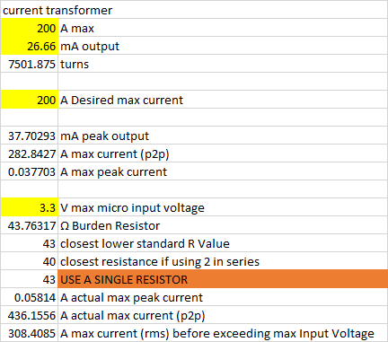
Here is how I do the maths:
You have a primary current of 300 A
You will get a secondary current of 300 A × 13.33 mA ÷ 100 A ≈ 40 mA
( So far, you are correct.)
You want that current to generate a voltage of 1.6 V (for the emonTx Shield) across the burden resistor,
(Your Shield accepts 5 V input peak-peak. After allowing for tolerances, 1.6 V rms is a good number to design for.)
Therefore you need a resistor of 1.6 V ÷ 40 mA = 40 Ω.
Choose the nearest available but lower value, 39 Ω.
Almost correct! You can have a parallel combination of resistors provided that the resulting effective value is correct. Having two resistors in parallel (one inside the CT and another inside the Shield) lowers the effective resistance value, not increases it. There is already a burden resistor on the Shield’s PCB, but it is the wrong value, and it is too small. As the value you need is higher, you must remove that resistor (33 Ω) and replace it with a 39 Ω one.
But wait: the value you need is the next value available, so do the maths but this time in reverse to calculate what your maximum current will be if you don’t change the burden resistor: It will be 354.5 A. You might feel that it is not worth changing the resistor. The maximum current reading will be 18% higher than you intended, the only consequence is that you will lose a little resolution at low currents. Only you can decide if it is worth changing the resistor.
Of what: The CT? You MUST have a.c output. You will read nothing if you have a d.c. output from the CT.
Is the voltage output caused/decided by resistor, if so, when i select the option of 1V output (on the website) it would mean that it would be pre installed with a resistor/burden to make it 1V at its maximum 300A in my case? which would make sense now i think about it that i need to provide the maximum expected amps and desired output V so the correct resistance can be worked out
I also did the reverse using the 33 ohms value (preinstalled in the shield), so if i using the same 300 A input as before i would get a 1.32 V output on the primary, form my understanding would be OK for the shield. Not quite 1.6 but close
i think my biggest confusion is the way the data/options is displayed on that website…
The AC/DC question; makes sense what you say, just got confused as some were listed as DC output… I mean theres AC Amp to AC Amp, AC Amp to DC Volt and AC Amp to AC Volt
Exactly. And with the correct value of burden resistor inside the CT case, you must completely remove the burden resistor on the Shield PCB.
But if you ask for 1 V at 300 A, then you will not be using the full range of your input. It will actually read up to 480 A. You’d be better asking for a 200 A version with a 1 V output, or the 400 A version with the 2 V output - the same thing. (Yes, it would be OK, Bill Thomson has been in contact with Magnelab!)
I am an Electrical Engineer, and to me, only one of those is a current transformer - the ac current to ac current one. All the rest are current transducers because they convert current to something else.
Our line is rated at 200A but we have seen it spike up to 230 or so.. i went for 300 to account for future expansion, but from what you say theres a range, so maybe stick to 200 A @ 1V then, but curious as to how you worked out the maximum.
Your Shield will accept a maximum of 1.6 V rms (actually, probably a little more but that cannot be guaranteed), so then it is simple proportion: 300 A gives 1 V, 480 A gives 1.6 V.
Magnelab assure us that the CT’s are good to a substantial overload. If you look at the current and voltage options, you’ll see that the same CT can be rated up to 800 A @ 5 V output. That implies a VA rating of 800 A × 13.33 mA ÷ 100 A × 5 V ≈ 0.533 VA, so it is easily capable of delivering anything you ask of it.
3x CT unberdened, taken care of by the resitors ^
https ://www.aimdynamics.com/product/sct-1250_split-core-ct/?attribute_pa_amp-rating=no-burden-resistor
$48.00 each
$144.00 total (£114.25)
Grand Total: £ 414.375 – £ 331.5 ex VAT
man that added up quickly
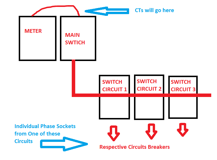
A quick question, does it matter where I pull the sockets (for the AC-AC adaptor) from, I ask because we have a 3 ‘circuits’ coming off the bus bar going to different production areas, the goal is to measure the the total, so the CT will be placed right before the main circuit on/off switch (between the meter and the bus bar), but do the adaptors matter say if i have them coming off a specific circuit, I’m hoping it doesn’t matter as this makes placement much easier!
I think your burden resistor is a little high. When you subtract allowances for component tolerances etc from the 3.3 V peak to peak, I get 1.1 V rms as the value to design for. That gives me 41.26 Ω, so I would go with 39 Ω, giving you a little over 210 A maximum current. With your 43 Ω burden, I could not guarantee undistorted readings from a pure sine wave above 192 A. If that’s OK with you, fine.
Not really. You want them on a circuit where there are no large loads and as close as possible, so that there is minimum voltage drop in the cable between the bus bars and the ac adapter.
If you don’t have a programmer, you might want one to reload the sketch after you’ve changed the calibration values, which will be wrong because you’re using a different CT and burden. Alternatively, you can calibrate in emonhub.conf (local emoncms) or put a multiplier in the processing chain in emoncms.org.
OK, I thought as much, but does the load on the the bus bar be the same as that of all the 3 circuits. Initially i was going to have a 4th breaker box direct from the bus bar just for these sockets… but if what i say my understanding is correct then would it matter since the other 3 circuits are still coming from bus bar… maybe I’m just confused here
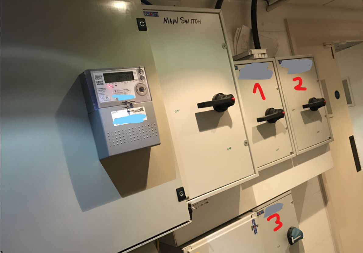
I attached a picture for easier understanding as my wording could be incorrect :s
1 and 2 here are the main consumers, 3 powers stuff like office sockets / lights ect… so to keep the costs down I was thinking of pulling the sockets from their own Circuit breakers coming from number 3 which is about 2 meters away.
Then the alternative was adding a 4th box (in this case a circuit breaker one) straight from the bus bar..
If distribution board 3 only has “office lights and sockets” you should be fine taking the 3 sockets from there, 1 and 2 may be slightly less suitable depending on how heavy the loads are on them, but 3 is close enough (electrically) and unlikely to have a voltage drop of any significance.
When installing those sockets you should consider hiding them away in an enclosure.Tthis is not only tidier and less likely to get unplugged, it is also safer and less likely to contravene any regulations (or bad practice) about having sockets from different phases in close proximity due to the potential 415v across any 2 sockets in a fault condition.
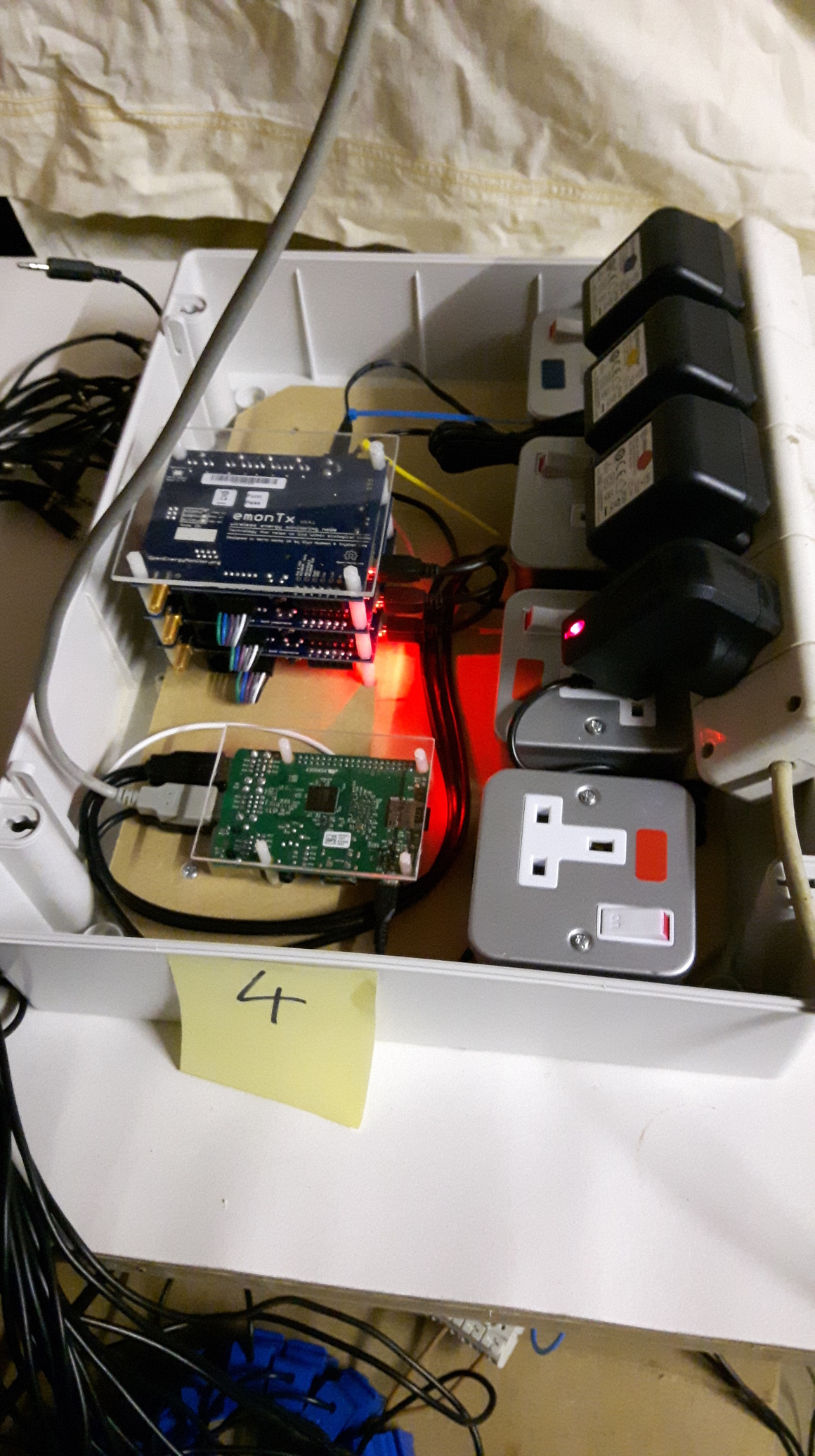
I have installed a fair few 3phase systems and I usually do something like this (excuse the 4way extn lead, this pic is from the test bench not installed on site)
Although I have now progressed to using 2 smaller enclosures to separate the high voltage stuff from the monitoring electronics as it is more flexible to locate than one big box and the Pi runs cooler without the heat from the 4 PSUs
This is a later monitor box, the 4 sockets (2single + 1double for the 5vdc too) are now put in a separate box by the sparkies doing the electrical install.
ohh thats a nice setup, I was planning a similar thing too putting them all in nice contained box, but i need to get all the technicals out the way first hehe
Yes, that particular circuit is mostly stuff like that… tho I believe there are some bigger things hooked up to it now, think some heaters were added… but it is the lowest load out of the 3…
I see you have your Tx powered by the base… interesting, any reason for this? why not just use the AC adaptors for both?
As Dave asked, you using wireless modules or the serial coms, I initially wanted this, cause its cheaper (no wireless module needed) and since everything is close no real requirement for it…