yh I’ve orded 3 from the openEnergy shop, ill be happy just to take some readings… and will ebay refund the fake ones… even if just cause there fake haha

yh I’ve orded 3 from the openEnergy shop, ill be happy just to take some readings… and will ebay refund the fake ones… even if just cause there fake haha
well i have some problems 
the new adaptors arrived and are working beautifully
but 2 of my CT have Irms readings of values like 0.17 or 0.06
only CT 3 has anything that looks like its fine… mind you CT 2 is on the same phase as CT 3 ( as i was testing ) im thinking soldering issues somewhere on the jacks… or the resistor… but before i venture into the that was wondering you guys take on this?
Regards
Fabio R
Without context or explanation it difficult to know what to say!
Do you mean “2 of my CT” or do you mean “2 of my emonTx’s”?
Are the CT’s attached to a cable?
Are they all attached to the same cable?
Is the cable powering anything?
What values are you expecting?
What are the numbers? I’m guessing the 1st value on each line is the node id and the 3rd is voltage, is the 2nd one power? and/or the 4th current?
What is the range of your CT channels? are they still 100 amps or have you altered the burden?
Have you altered the sketch to suit? correctly?
The voltages are all different, have you confirmed they are correct? are they all measuring the same phase?
So does that mean you hare readings of up to 150amps (Irms) on node/CT 3 ? surely that cannot be right?
150.07 Irms x 250.58 Vrms = 37604.54 W apparent power, if the power is 18902 W thats a power factor of 0.5, that seems quite low, what’s the circuit powering?
As Paul says, nobody can really help you with just that information. If you look at Resources > Building Blocks and follow the instructions for calibrating the emonTx, then tell us exactly what you are doing and what your readings are, then maybe we can help you.
One other point… Were the two CTs that give incorect readings connected, i.e. plugged in, to the emonTX before the TX was powered on?
Hello all ![]()
soo many replies ![]()
yes i should of made things a bit clear, my bad ![]()
the output is as follows:
nodeID realPower Vrms Irms
the installation is a 3 phase and the CTs are all the same with the burden resistor changed to 39ohm as per previous discussion and all the help from all of you ![]()
200 Amps is the rated output.
Currently all the AC-AC adaptors are plugged into the same phase, just testing this for now to make sure it all works and any changes needed (calibration?) ect…
Sketch for all 3 nodes, only nodeID changes:
// EmonTx V3 Direct Serial example
// AC-AC adapter must be used with this example (highly recomneded for more accurate Real Power calculations)
// Useful for direct connection to Raspberry Pi or computer via USB to UART cable
// Forum thread: http://openenergymonitor.org/emon/node/3872


// Tell emonLib this is the emonTx V3
// - don't read Vcc assume Vcc = 3.3V as is always the case on emonTx V3
// - eliminates bandgap error and need for calibration http://harizanov.com/2013/09/thoughts-on-avr-adc-accuracy/
#define emonTxV3

// Include Emon Library
#include "EmonLib.h"

// Create four instances
EnergyMonitor ct1;

// Calibration values!
const float Vcal        = 268.97;     // Ideal Power 77DB-06-09 (UK Plug type) =  268.97
const float Ical         = 192.31;     // 7500 turns / 39 Ohm burden resistor = 192.307
const float Psft        = 1.7;          // Phase Shift/Cal?...

unsigned long lastpost    = 0;
const byte LEDpin         = 6;        // emonTx V3 LED
const int nodeID            = 1;        // node ID for emonHub

void setup()
{
  pinMode(LEDpin, OUTPUT);
  digitalWrite(LEDpin,HIGH);

  Serial.begin(115200);
  Serial.println("emonTx V3 Direct Serial (3 Phase - 1 Line)");

  // CT Voltage calibration
  // ADC pin, Vcal Calibration, phase_shift
  ct1.voltage(0, Vcal, Psft);

  // CT Current calibration
  ct1.current(1, Ical);

  lastpost = 0;

  delay(2000);
  digitalWrite(LEDpin,LOW);
}

void loop()
{

  // A simple timer to fix the post rate to once every 10 seconds
  // Please dont post faster than once every 5 seconds to emoncms.org
  // Host your own local installation of emoncms for higher resolutions
  if ((millis()-lastpost)>=5000)
  {
    lastpost = millis();

    // .calcVI: Calculate all. No.of half wavelengths (crossings), time-out
    ct1.calcVI(20,2000);

    // Print to serial
    Serial.print(nodeID); Serial.print(' ');
    Serial.print(ct1.realPower); Serial.print(' ');
    Serial.print(ct1.Vrms); Serial.print(' ');
    Serial.println(ct1.Irms);

//    Serial.print(' ');
//    Serial.println(ct1.apparentPower);
//
    // Humam readable to Serial
//    Serial.println(F("Phase Info: ")); Serial.print(F(" "));
//    Serial.print(ct1.Vrms); Serial.print(F(" V, "));
//    Serial.print(ct1.Irms); Serial.print(F(" A, "));
//    Serial.print(ct1.realPower); Serial.print(F(" W, "));
//    Serial.print(ct1.apparentPower); Serial.print(F(" VA, PF=")); Serial.println(ct1.powerFactor,3);


    digitalWrite(LEDpin,HIGH);
    delay(200);
    digitalWrite(LEDpin,LOW);

    // Note: the following measurements are also available:
    // - ct1.apparentPower
    // - ct1.Vrms
    // - ct1.Irms
  }
}
yes this was before, then i plugged the rPi power which in turn powers them all on ![]()
Yesterday I was about to leave work and just wanted to see if you guys picked up any obvious mistake i might of made… I’m going to plug the one CT that seems to have a somewhat OK reading into the other nodes and see if they pick up a reading… so i can rule out nodes as being the problem… and then maybe check the CTs somehow.
I appreciate all the time you guys have put into this ![]()
these power industrial type heat presses
soo nodes are all fine… as in i get similar reading using the same CT on all nodes as i tested on by one… qucikly checked the 3.5mm jacks in case i had soldered them the way around… looks good to me… so im all out of ideas
PS: I swapped previous CT3 into node 1 and as you can see still gives an expected reading…
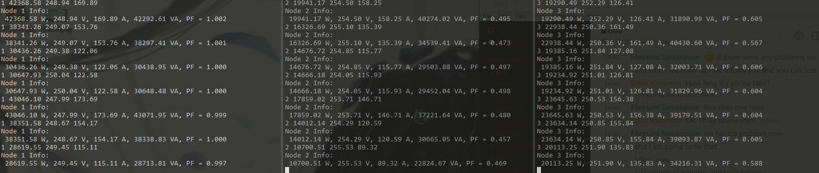
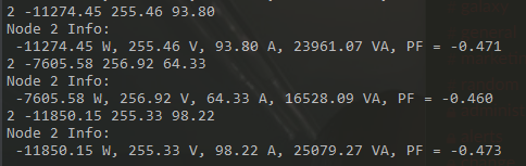
EDIT: some more output info
dont quite understand what is meant the power factor tho 
EDIT: last one is node 3, I’ve corrected nodeID since 
Power Factor is defined as the ratio of Real Power (measured in watts) to Apparent Power (the scalar product of voltage and current, measured in VA - volt-amperes). For a pure resistance, real and apparent powers are equal and power factor equals one. For a pure capacitor or a pure inductor, where the phase angle between voltage and current is exactly 90°, real power is zero even though apparent power will have some value, and power factor will also be zero. For a standard industrial induction motor, the power factor will be about 0.85 - 0.9.
It looks to me as if the CT on Node 2 is not on any cable, or you have a short circuit between the secondary wires of the CT, because those numbers for current, power and power factor are the sort of numbers that I see when testing an emonTx and there is a CT connected and detected, but no current is flowing. Node 3 might have the same problem, but it is not quite so clear to me that it is exactly the same.
If you take the CT (numbers 2 & 3) off the cable and measure the resistance of the secondary winding, what do you read? Depending on the CT, I would expect between 50 Ω and 200 Ω (Our ‘standard’ YHDC SCT-013-000 measures about 110 Ω, but it depends on the secondary wire size.)
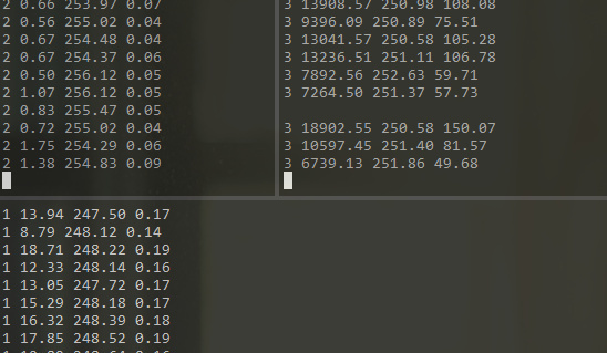
was playing around with CT 2 and got some readings, need to flip the CT but it seems either my soldering is bad (looks good tbh) or the jacks are faulty…
readings were about ~252 Ω when i managed to get one by fiddling with the jack internal bits ![]()
and all 3 ![]()
It is possibly more likely that the jack’s terminals with your wires soldered to them are shorting out once the cover is screwed on than “a bad connection” unless you have insulated them. It is wise to use heat shrink or at least a bit of insulation tape to ensure no contact or arcing.
With the emonTx disconnected from the power and the CT connected, you can check the resistance of the CT circuit across the burden resistor, if it is 0ohms there is a short, if it is around 39ohms the CT is open circuit, the expected value is going to be lower than 39ohms (you can estimate the value roughly by calculating the parallel resistance of the burden and inductor), maybe around 33 or 34 ohms if your CT’s are 250 ohm.
Paul, Is it a good idea to put a zener diode in for safety if your not using standard CTs?
indeed i did ![]()
with the CTs around the phase or not?
these do come with them factory fitted ![]()
Ahh TBH I had bought some smaller CTs from China and I wasn’t expecting to have the “all frills safety” thing and I was going to include one in the jack plug.
Yh its always good safety first!
I keep unplugging mine whenever i unplug them and such… better safe then sorry!
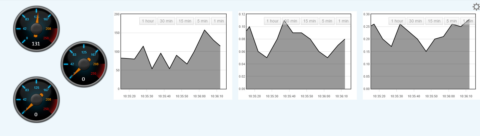
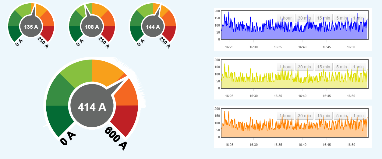
look at them go!! (AC-AC adaptors are still plugged into the same phase tho)
now if only i could figure this REDIS out… it breaks way to often
also, what do you guys prefer to use? PHPFINA or PHPFIWA for averaged?
Not on a cable, My bad I should have been specific but you shouldn’t really measure resistance on a powered circuit and the CT is effectively a power source.
I’d prefer Robert to answer that as it is a safety issue, I usually have in the past but not always. putting safety precautions in place is generally speaking always a good idea.
no problem ![]() ill give it a try tomorrow and see what it gives.
ill give it a try tomorrow and see what it gives.
Are they all powered by and measuring the current of the same phase? looking at you previous power factors it looks like you maybe powering or measuring accross phases.
??? I’m unaware of any issues with redis, tell us more!
phpfiwa is apparently being phased out and only available for backwards compatibility. How are you averaging ?.