Use the latest code not the precompiled binary files - program the controller using platformio.
This was a bug that is now fixed.
Use the latest code not the precompiled binary files - program the controller using platformio.
This was a bug that is now fixed.
Ok, then I will check all my non-working modules. ZERO’ed EEPROM means it is dead? Maybe I’m looking for a solution on the weekend.
Next time I will just reset the controller. Maybe it helps…
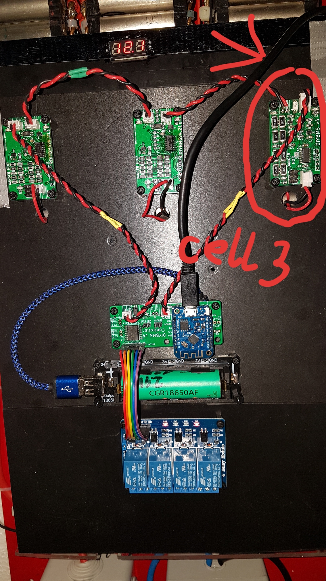
I have a funny guy here in my 3s80p battery. Module3 is playing funny jokes… 
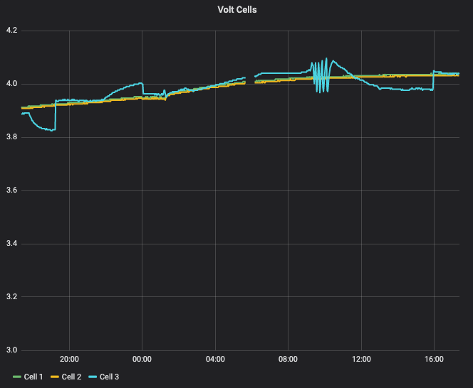
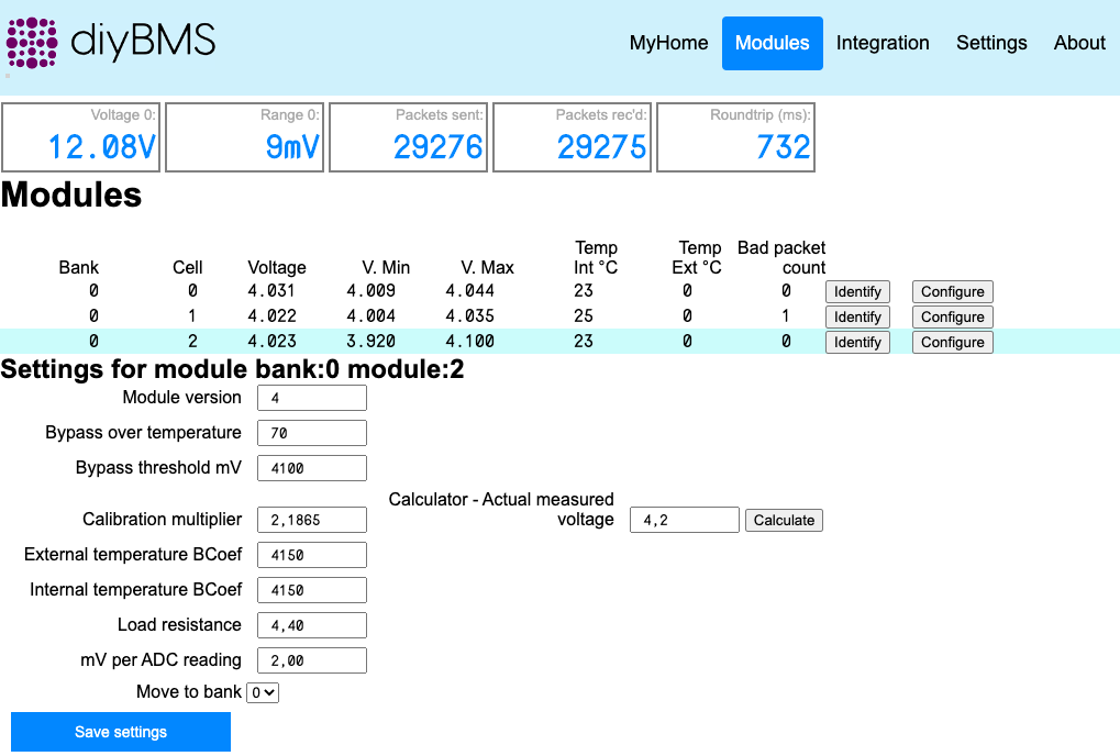
First I thought, my battery getting weak and the cells have problems to balance. But then I realized, that the actual voltage of all three packs are at the same level. Ok, so I typed the voltage into the field ‘Actual measured voltage’ hit enter. The value at ‘Calibration multiplier’ changed and I hit ‘Save’. So far so good. All three modules shows the accurate volt values. But after about 5 hours module3 randomly changed its values. The Grafana chart shows that module1 and module2 are more or less stable and module3 plays some funny games. I measured pack3 and adjusted the value several times, but a few hours later module3 got out of control.
The photo shows, that module3 is the one, which I soldered by myself. Module1+2 are ready assembled. Maybe a loose connection, which causes the instable measurements? Or is this a known issue and there is a simple solution? Or am I doing something wrong?
It won’t be dead.
Ive had one module do the same to me and I thought it was electrostatic discharge which cleared the eeprom
ESD would more than likely damage or destroy the chip vice clear it.
I won’t say that it’s not possible, and many modern electronic components have built-in ESD protection, but it takes a discharge of ~3kV just to be able to feel it. So it’s quite easy to build up say 1 or 2 kV, and never even be aware of it. Unless a device has the aforementioned protection, a 1 to 2kV discharge is going to do some damage.
I’ve heard of nearby lightning strikes wiping the EEPROM of burglar alarms. Whether it was EMP or a mains-borne spike or earth currents, and how it got in (mains or sensor wiring) is anyone’s guess. What it probably wasn’t is ESD.
Thanks @Robert.Wall
The symptoms on the module I had wipe itself occured when I disconnected the battery cell and quickly reconnected it - no sparks or anything like that, but the module code was fine, the EEPROM scrambled.
I’ve not see the module lose configuration when in normal operation, does this align with anything else happening at the same time - charge kicking in for instance?
Hey Everbody,
i just found this Project and just want to Play a litte bit with it. Everything looks really nice.
But when trying to get started, it’s a litte diffcult.
So as i see, there is no Webshop or something else, where i can buy the Board or the needed Parts.
I’ve just downloaded the Source. Within the .brd File it should be possible to order the PCB.
(Im new with KiCad, just used Eagle).
So, is there any list, where the Parts i have to order are listed. I don’t know how to extract from the Layout & Board.
If Somebody has a Card to Order, it would realy help.
(Even if Shopping to Germany could be difficult).
Im realy Shure, im not the first how’s asking. But i cant find in this thread.
Thank you
Hey @Benjamin_Gross !
There is branch for ordering from JLCPCB - https://github.com/stuartpittaway/diyBMSv4/tree/jlcpcbassembly
There you can find two folders - Circuit and Controller Circuit.
Inside each of the folders there are Gerber files you can upload to JLCPCB to order PCB’s but also if you want them to add components, there are *bom.csv and *cpl.csv files to uplaod that will select needed components for your order and placed them on board for soldering.
There is also a video on YouTube on how to order diyBMS v4 boards from JLCPCB.

Use latest code, compile and program using platformio. Rst wifi dont work and now PCF8574 is NOT fitted, relay control not possible! message appear always, I change 0x38 to 0x20 before compilate
Wait just a gosh darn moment there. Are you saying we now order BOTH boards complete? Hot dog!
Edit: JLCPCB out of ATTINY right now. Wemos D1 mini pro on the way though!
Yes, I do wish they would stock the JST connectors for assembly as well!
The code for the relay hasn’t changed, are you sure you changed the correct address for the PCF chip?
The WIFI reset works, unconnect the jumper pin, power on and whilst the green LED is on (3 seconds) connect the jumper. If you don’t do in this order, the board is unlikely to boot.
Hey,
i am in Germany. I have about 15 BMS and 2 Controller PCB left and would love to share. You can PM me.
BTW Id love to see this BMS count the input and output Ampere.
What is the status of being able to keep track of current across a shunt(s) and keep track of SOC?
I have 2 shunts, one for the battery and one for the solar panels, and would like to know both.
I’m willing to help.
hi f0m3, unfortunately one of my modules has blown today and I need one or two new ones. How can I write you a PM? haven’t found the function here yet.
I also come from Germany
Anscheinend brauchen wir UserTrustlevel 1 dafür. Das kriegt man aber schnell 
https://blog.discourse.org/2018/06/understanding-discourse-trust-levels/
@Sid1
Sie sind bereits UserTrustlevel 1. Klicken Sie oben rechts auf Ihr Symbol und dann zweimal auf den Umschlag
You are already at Trust Level 1. Click on your Icon top-right, then twice on the envelope.
How did you destroy the module?