I had drawn too much power from the battery and the fuses (the small glass fuses) from the cells have blown. Now the BMS module is dead. It stops blinking when I put 3.8 volts on it and when I want to program it, nothing lights up either  I can’t see any marks on the board or anything.

I was going to do the same with the heat sinks, then realised if I did that, it would short the resistors
Yes it would, you might get away with an insulating thermal pad under it.
The coolers are provided with a protective varnish on the underside and I used double-sided thermally conductive adhesive tape. Unfortunately, only the module where the fuses have blown is affected. The other 13 are intact.

1 Like
Hi @Sid1, I’m always curious on how the module can be damaged if/when a cell is damaged.
I can’t think of a scenario on pulling too much current from a cell would damage the module.
Hi @stuart , if you want I can send you the module and you can maybe see what went wrong. Maybe it will help for later versions of the board.
Wonder if its high frequency ripple destroying the module when the batteries are under heavy load. Such ripple occurs with some brands of inverters.
So essentially that cell has gone open circuit and the only link completing the circuit is that cell module which is now connected, negative to the positive of the previous cell and positive to the negative of the next cell. With an inverter completing the circuit that module will see full battery voltage in reverse across it bar one cells voltage.
1 Like
I had already thought that. Therefore I will now install a 0.5 A fuse in the negative line to the BMS. The small glass fuses blow at 1.5 to 2.0 A at 4.2 V. I don’t know if that’s too much for the BMS?
Howdy Stuart. Its been awhile because shipping plus covid took a long long long time.
Thanks again for the project!
I had an issue with interference, but it turns out the modules were too close to my inverter. I’ve moved them away from each other and the modules have been stable. I’ve also calibrated them using a single large lifepo4 cell which provided a pretty stable voltage reference. They claim to be within about 8mv of each other. There are some noise incidents though, so I think realistically +/- 20mv. I tried the same with a single 18650, but it was all over the map, I was struggling to get it within a tenth of a volt reliably.
On to tonights issue and reason for not posting a success post. I have this relay board https://www.amazon.com/gp/product/B071K7ZLYL/
Work Voltage: 5V
Quiescent Current: 5mA
Max Current: 190mA
Trigger Current: 3-5mA
Low Level Trigger Current: 0-1.5V
High Level Trigger Current: 3-5V
When I try to power it via the board, the relays don’t actually energize, but I can toggle the states. When I power it via 12v, i cant control the relays.
I thought maybe it is because I got this instead of the stated chip: PCF8574T/3,518 U3 SOIC-16W_7.5x10.3mm_P1.27mm C7605
Near as I can tell, the only difference is the address (mine is 20, instead of what is in the code)
I’ve checked it, and the bms does put out a signal voltage of about 2.8v when it should be on, and 0 when it should be off. However, when I attach to the relay-board, it goes down to about 1v. Do I need a different relay board, or do i need to add transistors? This is happening with both of my relay boards, using 2 different BMS receiver circuits (same wemos)
Yes it will. The reason for using such tiny JST connections and wires is to provide that fuse, the wire should melt with a high load. I’m surprised there wasn’t a track burnt out on the module if it had the full battery current through it.
I’d go for 1A, the balancing circuit is about 650mA
Its the wrong relay board. You need one with relays rated at 5V not 12V as the Amazon Photo shows.
This looks like the one I have…
1 Like
Thanks. I was just trying to use what I had laying around. I’ve ordered a similar board. Should be here tomorrow. If that doesn’t work I’ll order the one you linked to.
Thanks again!
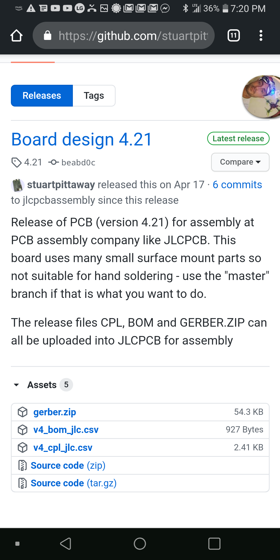
Hey guys I’m about to dive in to the diybms. I want to order about 40 or 50 boards from job PCB. If I use the included BOM how many boards will that make?
Hi Jon
the BOM thats included in stuarts Github is all the parts for 1 unit either BMS or Controler, depending on what you upload to JLCPCB.
so if you want say 50 BMS units then just upload the
Gerber
cpl
and bom files and make the quantity 50.
they will all be built from the same files.
Use the jlcpcb branch in GitHub and you can order exactly what you want almost fully assembled
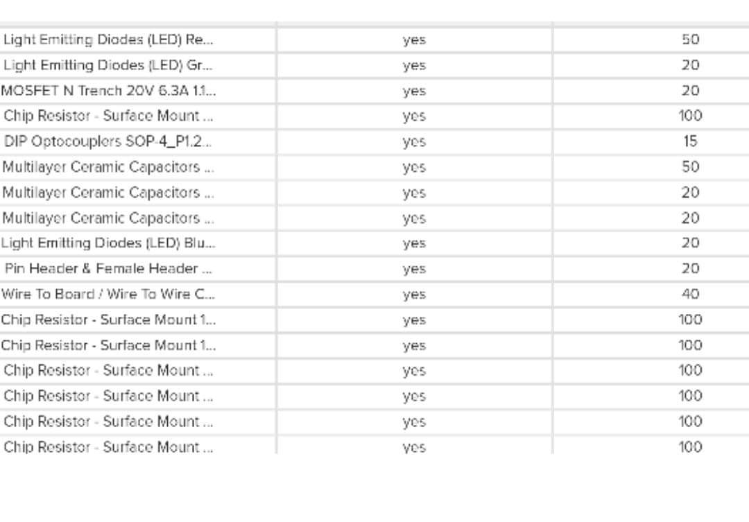
Hey guys thanks for the quick response. But there is no way that BOM I uploaded to LCSC was for one unit. The price came out to $40 and for all the items there is a large quantity… I used the file v4_bom_jlc.csv
Screenshot
Download the zip. Git clone won’t get you the right files. For your boards, one controller per however many circuits you want. I’ll be doing 5 controllers, 30 circuits. That’ll give me four 7s units with a couple spare controllers and circuits.