will jlcpcb ever get the attiny841 ?
Hi Marius
Is there any chance you can make a tutorial with the steps you followed to make it work?
I followed the steps from the previous and still cannot make it work.
Thank you
Both Mouser and Farnell have them available in the UK and they are actually cheaper than LCSC/JLCPCB. I might just purchase the ATTiny841 and solder them to the boards myself.
Those ordering from LCSC/JLCPCB how long is your delivery taking and where are you based
Thank you Stuart for your great work with the DIYBMS!!
I’m looking for help in trying to get my set up going. I cannot get the ESP Controller to connect to a cell module. The attached picture is my simple test setup. In this case with just one cell board connected. The cell boards I’m using are V4.21. They are built and populated by JLCPCB (with the exception of the ATTiny and D1 that I soldered on myself/ The ESP Controller board (V4) is also entirely populated by JLCPCB except for the thru-holes.
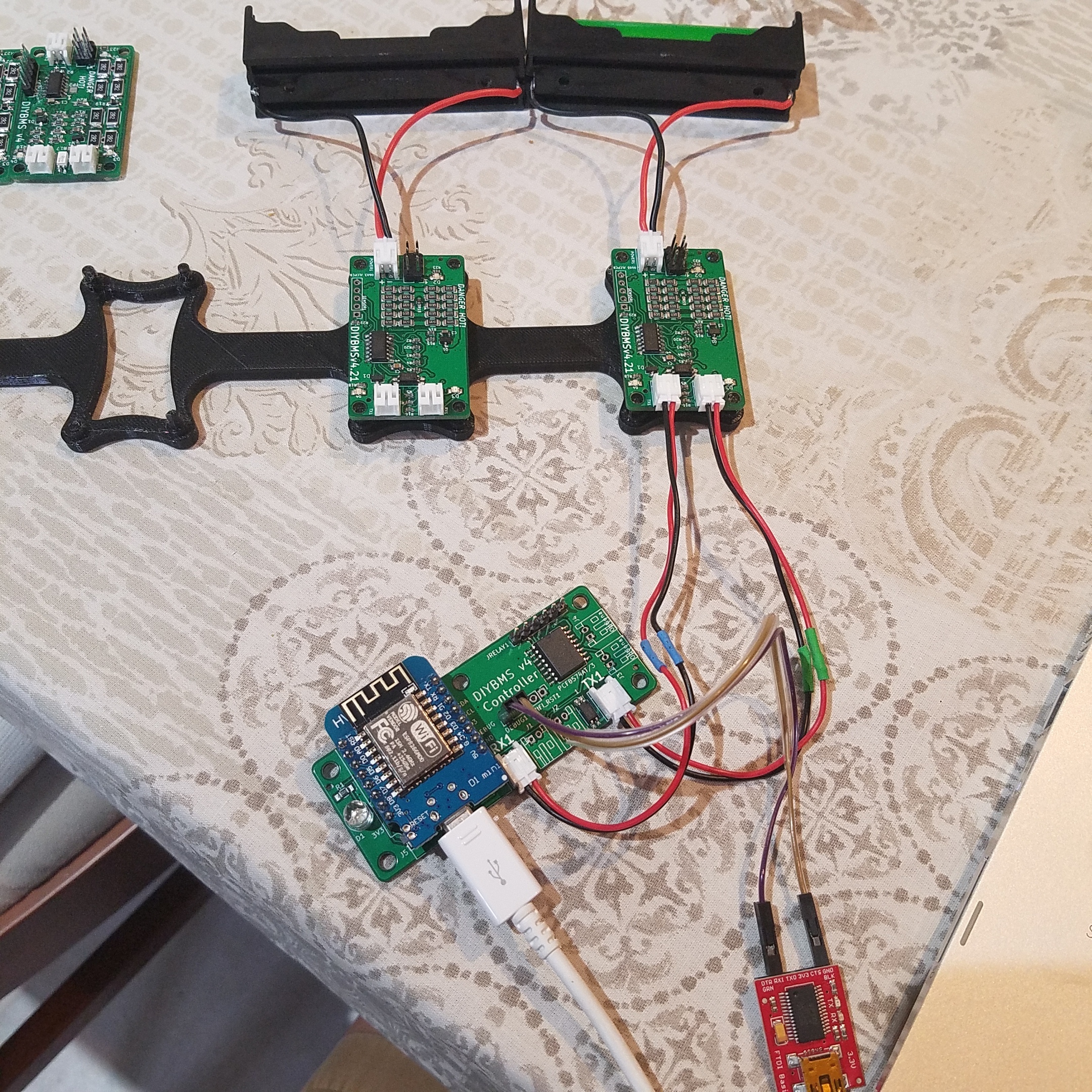
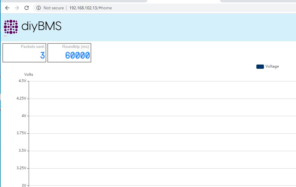
This is what I’m getting from the ESP Controller web page.
My debug log is below:
=~=~=~=~=~=~=~=~=~=~=~= PuTTY log 2020.05.21 23:31:52 =~=~=~=~=~=~=~=~=~=~=~=
Found pcf8574
Connecting to WIFI
Connecting to Wi-Fi…
mode : sta(84:f3:eb:e6:7c:73)
add if0
scandone
state: 0 → 2 (b0)
state: 2 → 3 (0)
state: 3 → 5 (10)
add 0
aid 5
cnt
connected with xxxxxx, channel 11
dhcp client start…
ip:192.168.102.19,mask:255.255.255.0,gw:192.168.102.1
Connected to Wi-Fi.
3. Connected IP:192.168.102.19
Requesting NTP from time.google.com
Got NTP time: 03:32:03 22/05/2020
S:80/1/1=0 0 0 0 0 0 0 0 0 0 0 0 0 0 0 0 =925/Q:2
S:80/3/2=0 0 0 0 0 0 0 0 0 0 0 0 0 0 0 0 =7301/Q:1
Rules:0000000100=
S:80/4/3=0 0 0 0 0 0 0 0 0 0 0 0 0 0 0 0 =CA8E/Q:0
S:80/1/4=0 0 0 0 0 0 0 0 0 0 0 0 0 0 0 0 =C5D6/Q:1
S:80/3/5=0 0 0 0 0 0 0 0 0 0 0 0 0 0 0 0 =9799/Q:0
Rules:0000000100=
S:80/1/6=0 0 0 0 0 0 0 0 0 0 0 0 0 0 0 0 =EDBD/Q:1
S:80/3/7=0 0 0 0 0 0 0 0 0 0 0 0 0 0 0 0 =BFF2/Q:0
pm open,type:2 0
Rules:0000000100=
S:80/1/8=0 0 0 0 0 0 0 0 0 0 0 0 0 0 0 0 =34AC/Q:1
S:80/3/9=0 0 0 0 0 0 0 0 0 0 0 0 0 0 0 0 =66E3/Q:0
Rules:0000000100=
S:80/1/A=0 0 0 0 0 0 0 0 0 0 0 0 0 0 0 0 =1CC7/Q:1
S:80/3/B=0 0 0 0 0 0 0 0 0 0 0 0 0 0 0 0 =4E88/Q:0
S:80/1/C=0 0 0 0 0 0 0 0 0 0 0 0 0 0 0 0 =647A/Q:1
S:80/3/D=0 0 0 0 0 0 0 0 0 0 0 0 0 0 0 0 =3635/Q:0
Rules:0000000100=
…
Also, I flashed one of the cell boards with the “TestDebug” binary and got the the following readings:
Sensor1 Readings
5 - 4 = 3.89 Volt
5 - 2 = 1.26 Volt
Battery = 4.00 Volt
I would really appreciate any help or insight. I must be missing something very simple.
Thank you!!
Does the green LED flash on the module? If its receiving a message it should flash.
Have you tried connecting more than 1 module?
I would think its a soldering issue, there is probably a bad joint on one of the ATTINY pins.
PS: Like the 3d printed rails!
Hi
I want to thank Stuart and the team thats contributed to this project as this is a really nice system.
I have recieved my cell modules and controller from JLCPCB i had the cell modules made but still have to solder the controller board.
The problem i am having is i am unable to flash my cell module, i am using platformio and a USBTINY as the programer.
I was following Adam Walsh video to a tee but i get the following error avrdude: Error : could not find USBTINY device 0x1781/0xc9f. I have been trying to get my head around platformio as not used it before.
I beleave that i have installed all the software i need to do this ie platformio, git client but not sure if correct one, and i have previosly use a clone uno so i am assuming the driver for the USBTINY are there on this machine. But i have also downloaded a driver anyway to see if that would help.
I have looked at this formum and i did read that someone had the same problem and from memory i think Stuart said to hardcode the com port. the problem i have is one i cant find the post to find the command and also how do i know what com my USBTINY is plugged into ? is there a way to find out ? (silly i know sorry)
Any help would be very much appresiated.
Mike
Im in the Uk
order placed on the 13th should have them by friday there currently in germany.
shipping is approx 5 days
like VinoVeritas said farnell have the aTTiny in stock that where i ordered mine from,far cheaper than JLC.
I have 50 BMS modules arriving and 5 controllers arriving i only need 14 and 1 controller so if any one want any let me know.
I’ll take 1 controller and 8 modules. But, I have no desire to solder the attiny. I’ll wait for JLCPCB to get them in stock unless you’ll send me the modules with the attiny assembled.
I apologize for the posting to this forum instead of a direct email. I’m not sure how to email you directly on this forum thing. I am john dot taves at pnwsoft.com thanks.
Thank you Stuart for the quick response.
Yes, I have tried to daisy chain more than one module. I have 4 of the V4 modules that I hand-soldered along with the 4 new 4.21 boards populated by JLCPCB. In all 8 cases, they all show the same:
- Each one flashes the Green LED a few times every 10 secs until I plug them into a powered ESP Controller board.
- When connected to a fully charged 18650 (at 4.2V), each module will trigger dump mode (Red LED) in intervals with the power resistors getting hot
I will double check the solder joints on the ATtiny. Thank you for the suggestion.
I ordered populated boards from JLCPCB the other day. DHL lost my package. Arggg!!
1 Like
@stuart just wanted to say thanks! I completed my POC setup with some headways. No problem getting the boards ordered and adding a few out of stock components by hand. I’ll be integrating into my powerwall next. Thanks again for your time and effort!
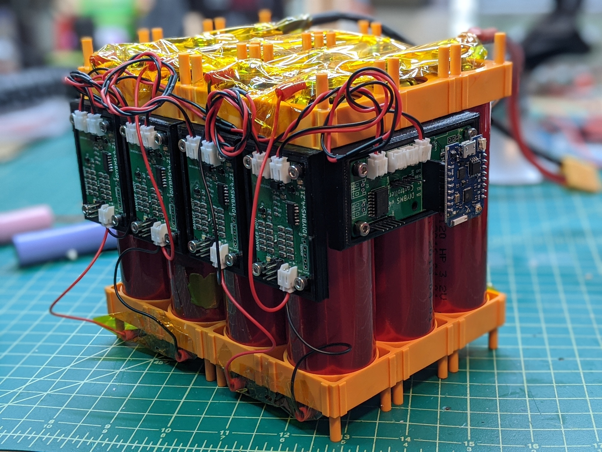
Thats nice, good work.
Okay, so this is the clue. They flash every 8 seconds when they are not connected - this is correct behaviour.
When connected to the controller if there is no green LED, then that is likely the module thinks its on a different bank configuration. Try changing the controller settings to have 4 banks (you will get some errors on screen) but the modules may now appear.
If they don’t on each module try clearing the EEPROM memory (google for program code to do this). Also make sure you have programmed the fuse bits.
I use the USBASP which is different to the USBTINY. Did you change the platformio.ini file to alter the line
upload_protocol = usbasp
to
upload_protocol = usbtiny
Hi all, I recently came across a new PCB assembly service, CNOSPCB (https://www.cnospcb.com/), has anyone used it before?
I’ll be interested in taking 1 controller and 4 boards.
That looks like a clone of JLCPCB website !
Thanks Stuart, yeah i changed the upload_protocol = usbtiny.
I have order a USBASP progamer v2.1 lastnight in hope that it will sort it out, and should be here today ?
Are there any tips or anything i need to prep before hand IE load any additional programs or Drivers, or is it just a case of plug and play.
Many thanks again Stuart
Just plug it in - there are a lot of clone USBASP programmers on the market and some need a firmware upgrade to work reliably.
[https://blog.podkalicki.com/how-to-update-avr-usbasp-firmware-to-latest-version/]