Thanks for the appreciation.
The issue is created.
There is huge difference between SSR and relay controlled load. If you imagine relay controlled heater with few killowats it is not good for relay, inverter, batteries. Using zero-crossing SSR (SSR 25DA FOTEK) you can regulate power to load precisely without blinking your bulbs. And with some simple algorithm you can use as much power as your inverter can deliver.
After reaching float you can wait some time while balancing and then fire extra load with keeping current to the batteries with positive value (positive meaning charging batteries and negative discharging batteries) by regulating a load with SSR.
I orderd few pieces of ACS758 (https://lcsc.com/product-detail/Current-Sensors_Allegro-MicroSystems-LLC-ACS758LCB-100B-PFF-T_C82405.html)
Actually, for excess energy utilization I plan to use a separate controller which will read cell voltages from the DB and switch on/off DC heater elements (do not wish to put unnecessary load on the inverter) step-by-step: first 300W, if voltage is still high, next 300W and so on, and back when the voltage drops down. But this is another story and would be done much later, after solar station is fully running.
Regarding the Firmware: you mean from the hardware/JLCPCB Branch, releases, the binary files from 23.Nov. 2019?
But the jlcpcb branch has no code. Or do I get this completely wrong?
I also have ordered 15 cellmodules with the gerber, bom and cpl File from branch “jlcpcb” two weeks ago. Last week also ordered assembled ESPController. Looking forward to the first testing…!
There is no code in the hardware repo, take a look at the instructions, the code is in a separate repo.
I always use the master branch of GitHub - stuartpittaway/diyBMSv4Code: Software for diyBMS v4.
1 Like
Hi all, newbie here coming from Adam Welch’s YouTube channel.
Is there any documentation available regarding how the DIYBMS works and what its specifications are? I am just trying to figure out the DIYBMS would work with 4 X 3.2v LiFePo4 100aH cells in series?
Cheers.
Thank you
It should be find with that. Each cell monitor works in isolation and you set the top voltage that you want it to start balancing at. Once the cell hits that voltage the cell module will activate and start “bleeding” off current. The controller gives you a web page to configure/monitor the cell modules.
Thanks Nick. I have managed to get my head around the way the DIYBMS works, but what confuses me is how other BMSs are rated. For example, a ‘4s 100a’ BMS is suitable for 4 cells or modules in series, but what is the 100amp rating for and how does DIYBMS compare?
The 100 amp rating is the maximum current you can draw through the BMS. This is because those BMS can control the current draw to protect from over current and over/under voltage. The DIY BMS doesn’t have that ability, it just does balancing so doesn’t control power draw from the battery.
I understand now. That’s presumably because the BMSs I’ve been looking at with amperage ratings are used in EVs (bikes, scooters, etc) and can have huge draws from the battery. As long as my usage stayed within the charge/discharge rates specified by the battery manufacturer, I wouldn’t need a BMS to do that side of things.
Thanks for your help Nick.
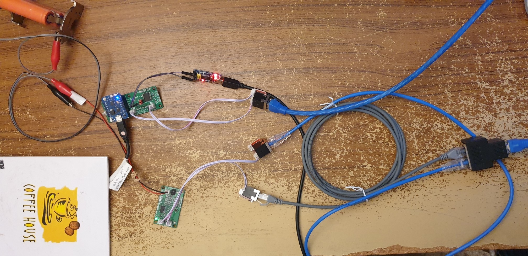
Since I moved my power source for the controller board, from my laptop USB, to battery powered USB (4S20P) with a stepdown converter 12V → 5V i keep getting CRC Errors… not a lot… about 3-5 per 5 mins.
The USB power is stable at 5V and nothing else but the controller and 4 modules are attached to the pack…
Any idea what can cause this? The wires from the controller to the modules are about 20cm long, and as mentioned when I run the controller from the laptop USB, I get no errors at all…
I was thinking that maybe I need a large cap before my USB output? (it can’t hurt…)
But thinks it a bit strange…
My boards are the latest jlcpcb-kind.
Any help appreciated…
/Heino
Tell who from what source connects power to controller. How to power it from battery?
For people who are interested in having modules built by JLCPCB, I’ve obtained a $10 USD discount for new orders.
All you need to do is email your JLCPCB username to [email protected] mentioning this forum and DIYBMS.
DISCLAIMER: I don’t personally benefit from this offer!
4 Likes
Thanks Stuart. I’m still waiting for them to get the ATtiny841 chips in before ordering, so that extra 10% discount will be great.
Hi All,
Any Ideas how long I can get before the communication starts to fail ?
I need to put the ‘controller’ outside my shed, (the shed kill all wifi signal ) and run a cat 5/6 lead to the 1 to2 ‘junction box’, it will have 7 slave units, but i’m just using 1 at the moment to see if it could work
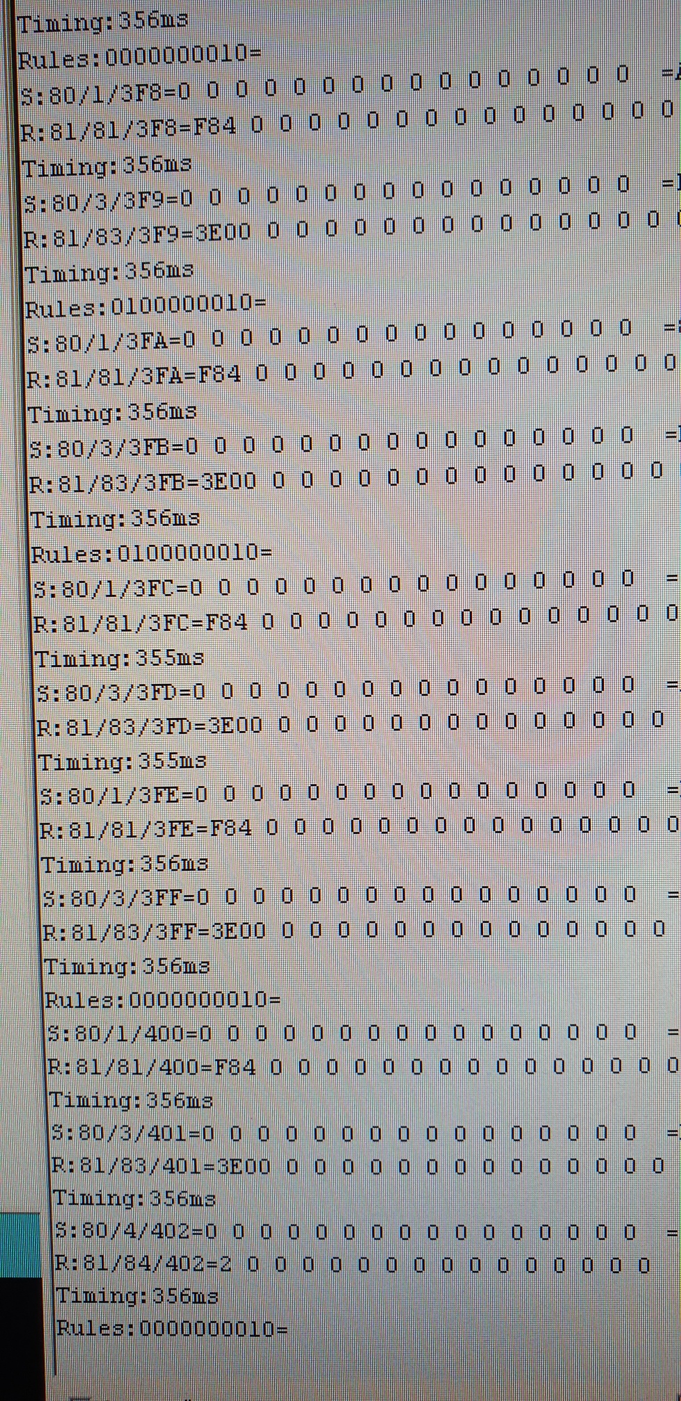
You want to keep the cables as short as possible, moving a wifi repeater into the shed would be easier.