My understanding is that the individual cell boards monitor the temperature of themselves to regulate the power that is drained from a cell that is high relative to the other cells. This is not a battery temp sensor to stop charging when near freezing, right?
Does the controller have an ambient temp sensor to shut off charging when near freezing? I did not see a rule for that in the video.
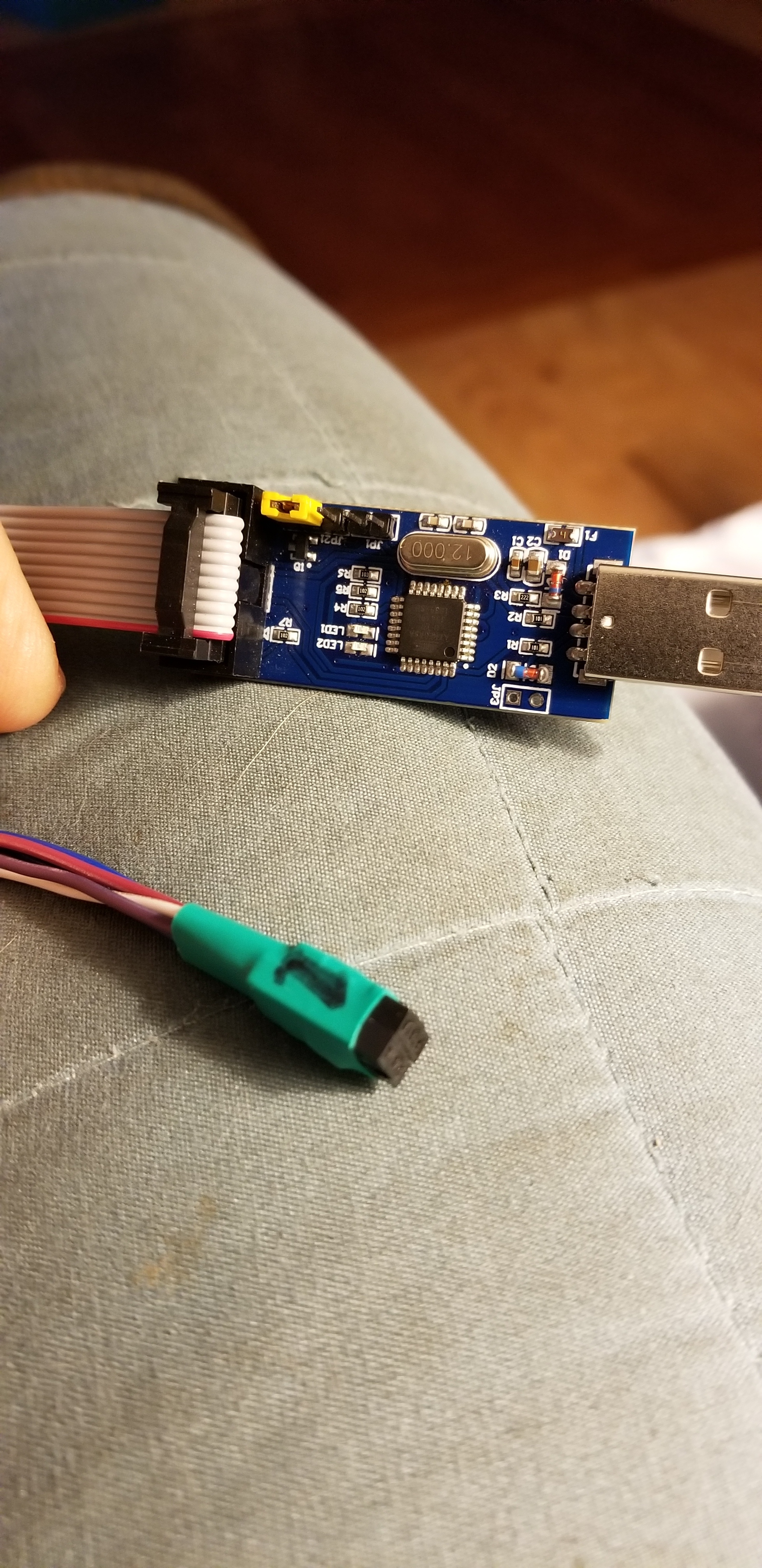
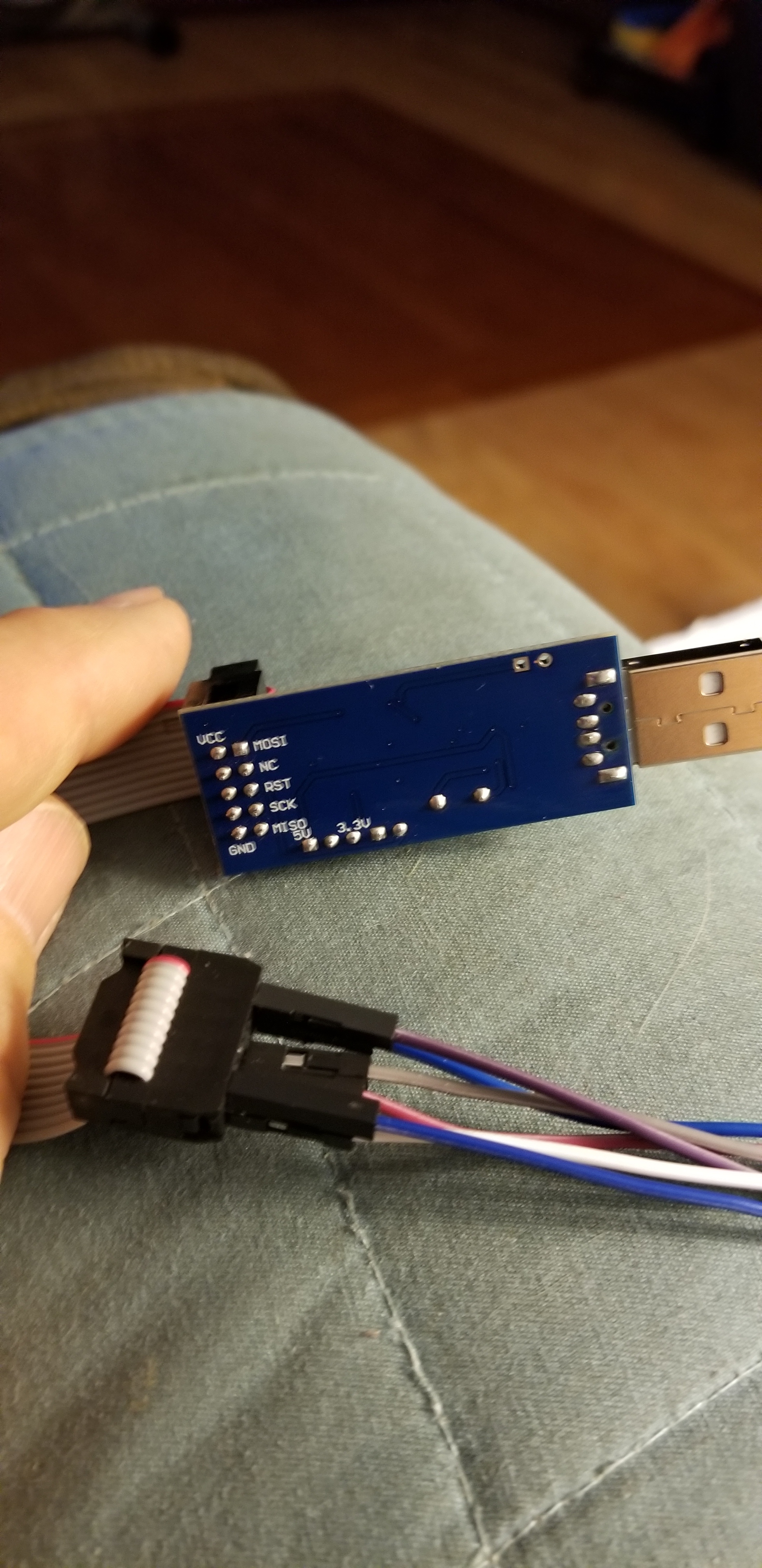
Both the relay board and the board that piggy backs on the controller are purchased separately, right? I understand the relay board, but am confused about the piggy back board. That’s some sort of arduino, right? What do I buy?
I will receive the v4.21 cell modules this week. I uploaded the pervious BOM so I will have to solder some of the components which is not a problem. R19 might be a little difficult with my old @ss eyes though.
However I need to order the controller. I uploaded the gerber for the controller board. Should I wait for your update or can I have JLCPCB build it? I did not see the CPL and BOM for the controller. Is the controller a “hand solder” only build or SMT by JLCPCB?
But isn’t this measuring the board temperature, which can rise above ambient when it is attempting to balance? Thus isn’t this a bit risky if the goal it to turn off charge sources near freezing?
Is there a temp sensor, or temp input on the controller to measure pack temperature?
Dear @stuart ,
I would like to share some suggestions / feature requests about rules. Maybe you would consider to put some of them in the future releases:
Add an internal over temperature rule to start cooling fan for the bms (Example: cells modules are installed separately from cells, all together, lets say in a box. With such installation it is easy to organize a cooling for them to make top balancing more efficient for large packs. Also in such case the interface/communication wires are as short as possible to minimize interference. A rule to start cooling would be nice to have in this case)
Individual cell over temperature (external) °C - it would be great to have this rule 2 times to configure HIGH and HIGH HIGH limits. HIGH limit would be used to switch on cooling fans in the battery compartment and HIGH HIGH - as a main trip signal to disconnect the battery from all devices.
Pack under voltage. The most reasonable use for this rule is disconnecting and connecting back to the battery inverters. I saw somebody already suggested to put a time delay for rules, but I would like to extend this subject. Normally for such application 2 set points are used: switch off set point and recover set point. Time delay would also be great (to cover start loads) but not enough, from my point of view. Example: 14s battery + grid tie inverter with limiter - the inverter itself will normally have a battery discharge protection, however it make no sense to “dry run” an inverter if the battery is discharged because it will only consume power from grid (yes, not much, but still); so, it would be nice to switch off the inverter lets say at 44V and connect it back only after battery is recharged to lets say 49V. Using this rule “as it is” with only one set point make for me little sense, because it would be jumping back and forth all the time.
Pack over voltage (mV) - similar thing as above but for burning the excess energy (to heat the water for example). We can switch on the relay to turn on the water heater at Lets say 57,5V and switch it off at 56V.
What would you say? Can you please share your thoughts about this suggestions?
As for me personally, I plan to use below rules to trip an MCCB for battery general protection
Communications error
Individual cell over voltage (mV)
Individual cell under voltage (mV)
Individual cell over temperature (external) °C
And would also like to have 2 more temperature rules for cooling BMS boars while balancing and cooling battery compartment. I can probably use separate thermostats for this purpose, or modify code a bit to add this features myself, but I think it would be a nice feature to add to the DIYBMS functionality, especially since all necessary data are already available and it looks like implementation should not take too much effort.
PS: still waiting for some components to finish my boards and start playing with them…
Hi Yar_Leo, considering 4) I got your point, in the Czech Republic many people use similar solution based on reading battery voltage (Vytěžovač • Fórum | MyPower.CZ)
But from my point of view is much better use SSR with PI(D) regulator and with current sensor try to keep current from batteries near to zero.
Thanks for the suggestions @Yar_Leo, I agree most of these are good ideas. So we don’t lose them, can I ask you to create a GITHUB issue with the suggestions for me?
Yes SSD and a PID is a good way to use the power available. I doubt that I would introduce this into the controller though as its a bit out of scope. Nothing stopping this being driven from the relay or another controller board output though.