I think it depends on what you mean. If you are going to have 2 batteries of 4s20p then you would need another 4 modules, if you are going to have 1 battery of 4s40p then I think the 4 modules you already have will be enough. I’m assuming you are using old 18650s here, if you are using something bigger (like Leaf modules) then you might want more burn-off ability.
If you need help on the ESP32 I can help you there, I have a version of the v4.0 code that was compiling for the ESP32 but I haven’t tested it fully on actual hardware. I had also added the shunt reading support via I2C as well.
Keep in mind there are a few gotchas on the ESP32 compared to the ESP8266, most notably the crashing of the ESP32 when accessing flash (ie: SPIFFS) when an ISR is active (ie: pin change ISR). The second CPU core is nice but it can create a lot of headaches.
I would suggest looking at the ESP32-S2 as it is a single core ESP32 that is the successor for the ESP8266, it offers almost all functionality of the ESP32 but has a number of silicon bug fixes and a lot more GPIO pins available!
My plan is to add packs of 4S20P in parallel to add more capacity as I complete building the packs… it will end up with 3 maybe 4 times 4S20P. (does it make sense?)
And yes it’s 18650s…
Hi I would like someone to help me
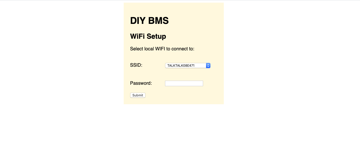
There is a problem with the wifi connection.
-
I used the precompiled firmware to flash the wemos d1 mini pro and used the NodeMCU-PyFlasher to do the job. It could connect to my router and i could login, but it wasn’t communicating with the modules.
-
Finally I managed to flash it using platformio (the reason I could not do it before was not changing the port) Now the controller communicates with the module because the green leds are flashing in sequence.
Now the problem is that when I connect to the controller so I can set the connection with my router it doesn’t connect and I still can see it in my WiFi list.
here is a short video
is my router a problem or there is something else
Thanks
Great News. I’ve been in talks with jlcpcb about adding the ATTINY chip to their SMT library and they have. It is now possible to get the boards fully populated so that you only have to solder the pins and connectors. It’s not cheap however as each ATTINY is about £1.50! It’s far cheaper to order them locally and solder them yourself but for those who would rather have it done for them, you now have the option. One thing to note is that the ATTINY placement is out by 270 degrees rotation. @stuart I have modified my local copy of the placement csv to give it 270 degrees of rotation but as I don’t have a fork of the hardware repository, can’t do a push. Can you make the update to the file in github?
1 Like
10K is fine, but you would also need to swap the other “half” of the resistor think its R21 - 47K to 10K (but you need to check!)
Does your router support wifi on 2GHZ and 5GHZ channels ?
Well done - I asked and they ignored me!! $1.89 a chip is expensive though, price break at 10 units - but they only have 33 in stock at the moment.
Assembly for 25 boards is now $3.08 USD per board plus shipping.
I’ve updated the CPL file to rotate the ATTINY correctly. Its in the JLCPCBBRANCH.
Note I have removed the 4.2 branch - the JLCPCBBRANCH replaces it
1 Like
I wonder if that is before or after my 30 boards I just ordered this morning! ![]()
2 Likes
Hi All
This is a Great project, Excellent work Stuart.
Iv just orderd 50 BMS Boards yesterday, luckly i didnt go for there ATTINY, a bit expensive.
I had some trouble with JLCPCB as i orded the controller and BMS boards at the sametime and they canclled my 1st order??
but after a few emails explaning they where two seperate items they approved it and its now in production.
so ill just have to watch out for the ATTINY placement?
Hi Stuart and thank you for your reply.
My router supports both 2.5Ghz and 5Ghz
And I think the router is not the problem as I checked it at my works WiFi and it’s still not connecting to it.
Still unable to program either the controller or module.
latest errors:
Module: last response from PlatformIO:
avrdude: 376 bytes of flash written
avrdude: verifying flash memory against .pio/build/attiny841/firmware.hex:
avrdude: load data flash data from input file .pio/build/attiny841/firmware.hex:
avrdude: input file .pio/build/attiny841/firmware.hex contains 376 bytes
avrdude: reading on-chip flash data:
Reading | ################################################## | 100% 0.22s
avrdude: verifying …
avrdude: verification error, first mismatch at byte 0x0000
0x00 != 0x1d
avrdude: verification error; content mismatch
Controller error:
Changing baud rate to 921600
Changed.
Configuring flash size…
A fatal error occurred: Invalid head of packet (0xE0)
*** [upload] Error 2
Try dropping the controller baud rate down
Have you seen this issue - I think this may be your problem.
I think I just programmed 2 modules, need to program controller to be sure.
I compiled the HEX file in platformIO (windows 10) and used Win Terminal to run avrdude command line using ArduinoISP (UNO).
ex: avrdude -F -P com2 -b 19200 -c avrisp -p t84 -v -e -U lfuse:w:0b11100010:m -U hfuse:w:0b11010110:m -U fuse:w:0b11110100:m -U flash:w:firmware.hex
UPDATE: Controller programmed as normal and OK in platformIO. However, no blinking lights on the two modules and I cannot get the controller in browser???
UPDATE2: Changed to 4m on controller, now working (I am connected) but no modules??
PlatformIO from windows:

Yes I did checked it and I thought it would not be the problem because I purchased the wemos d1 mini pro which has 16Mb. But I think I have been tricked and it is 4Mb.
So now I flashed it again and it works perfectly
Thank GOD!!! I’m on the way up. Changed the USBasp programmer (jumper) from 3.3v to 5volts.
Bingo, loading modules no problem. First one is up! Yee Haaaaa!!!
What I did to recover:
- Program Arduino with ISP sketch
- connect to module and choose attiny841 for board without boot loader
- Programmer → choose arduino as ISP (attinycore)
- Set eeprom to delete
- Burn boot loader
- disconnect 6 pin and arduino from module board
- Connect module board to USBasp programmer
- PlatformIO to build (I had to use windows, mac with catalina would not work)
P.S. Not sure the arduinoISP thing is needed, I programed the last few modules just with USBasp programmer (5v).

I was going to suggest that the 4M d1 might be the problem but then when I saw
in the message I thought, “it can’t be that then”.
I’ve had another idea. If I attach 2 modules to my 80p cell then I need to have 2 fully populated boards including the ATTINY that are not that that cheap. Could there be some way to modify the board so that a second board populated without ATTINY (and potentially anything else not needed) could be slaved to discharge in line with the master board. I’m thinking along the lines of each board having it’s own connection to the cell so that all the current doesn’t go through the master board. I might have a go at modifying the design myself but my electronics knowledge is limited, I’m a software developer really.
theres alot of clone pro boards on ebay that say they are 16 but infact are 4mb, just swap the 4mb chip out to a 16mb https://uk.rs-online.com/web/p/flash-memory/1712222/ done this with many esp01 and cheap d1 mini v3