Did you bulid your own PCB?
no they were purchased from JLC PCB i just modded them to work with what i have at the moment
Dear Mr. Pittaway,
I was wondering if you would like to give a little advice on a project currently underway. Im a first year Electronics Engineering Tech. student and was inspired to build one of these electric long boards that are very popular right now. I’m on my last steps to completion and all that is left to do concerns a BMS. Ive looked at the pcb’s you can buy online, i even bought one. However, after watching a few of your videos you inspired me to do it myself. Is this something that is reasonable?
I would love any feed back
a fellow maker
-Clifford
Edit - removed “code” type formatting for readability. BT - Moderator
Please link and how you purchased them
on the github…
Is the size of you PCB is 50x30mm?
I give you a tip. I think it is a good way to understand this that you read all this post, and also all the post about DIYBMS v3.
1 Like
Thanks

Nick,
For me the connecting was no problem however when i see the page to select the SSID and enter the password an confirm the controller goes offline but is not connected to the selected network.
Any experience on this issue?
Hi @stuart. Would you update the schematic on your github with the new part, TL432G-A-AE3-R.
According to ‘Diodes’ the AN432ANTR is not recommended for new designs and I cannot find distributor in NA that has the device in single quantities.
Not that situation no. Did you get the network password wrong?
Done!
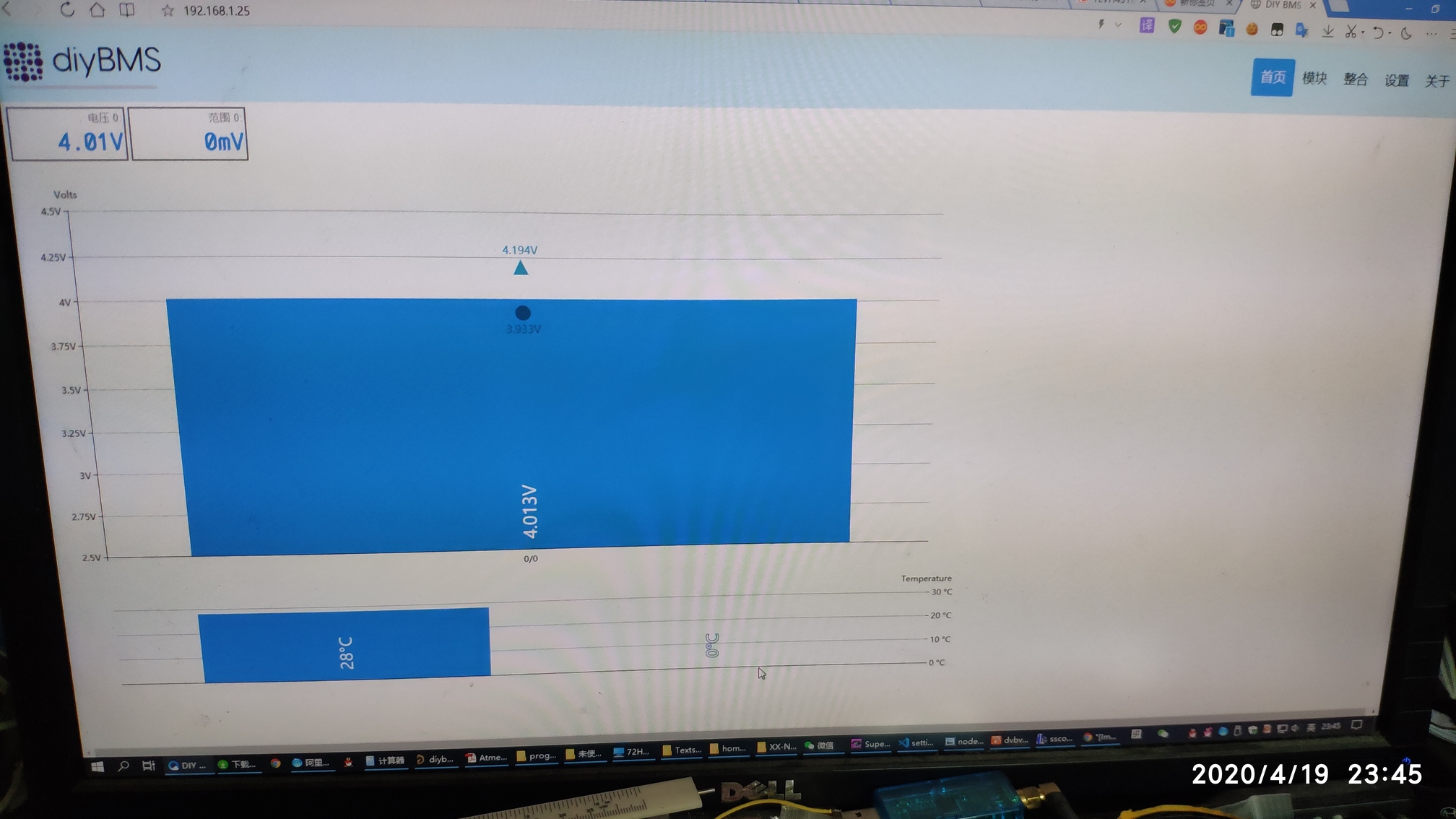
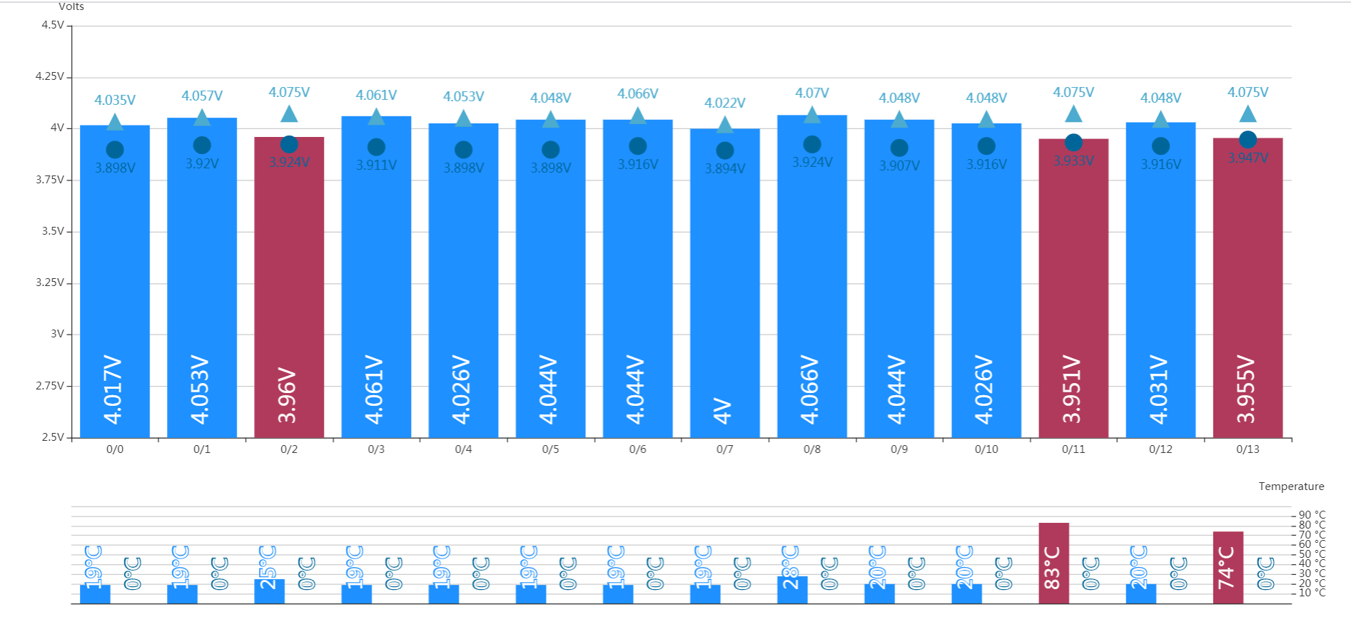
Running a balance at the moment and I’ve got the bypass temperature limit set to 45 (because mine has the resister/thermister backwards issue). So how come the temperature of the boards is reading 70 to 80 degrees? I’ve double checked the setting and it’s definitely set to 45.
Also: what is the difference between a solid red light and a rapidly flickering red light?
Glad you got it working - why did you swap to 5x 22 ohm resistors?
How will those handle the power and heat ?
I apologize for the newbie questions, but here goes.
Background: I want to figure out the ideal BMS for RVs. I also want to include some high school kids that are interested in this, and are sitting on their butts waiting for covid-19 to pass.
Just to confirm: This BMS does not have the main battery current running through it, so it can any size load/charge, but the charger and loads need to be shut off via the relays, right?
Is there a kit? I see that Stuart mentioned something like that last year.
I am more interested in understanding the circuits, theory, the software, and actually using it, than buying the parts and soldering. Is there a way to buy assembled modules?
My understanding is that there are 3 components. N modules for N cells, 1 controller board, and 1 relay board. Do all 3 need to be built, or is the relay board off-the-shelf?
I see the spread sheet for the module parts. What about the 2 other boards? I didn’t see spreadsheets for them.
Or to put this another way, is there a parts list that includes everything, including the wires?
If I want to put the kids to work building modules, what will I need? I watched DiyBMS v4 Module Build - YouTube and conclude I will need:
big magnifier
syringe thingy
some thermometer to get my oven set correctly
tiny soldering iron
tweezers
consumables solder, paste,
I hope to get a complete shopping list so that I can fit out a few kids to make this at their homes.
There is no kit per se. There is a gerber file that you can sent to jclpcb and they can create the boards for you and even pre solder most of the components (but not all) though you still have to hand solder a few bits.
No
Yeah but you don’t necessarily need the relay board, depending on what you want to do.
There isn’t a parts list that includes everything.
Depends if you get jclpcb to do most of the soldering for you or if you just order the bare boards and do the stuff yourself. I had to hand solder the ATTINY chip and the connectors and for that all I needed what a soldering iron with a fine tip and a holder with a light and lens.
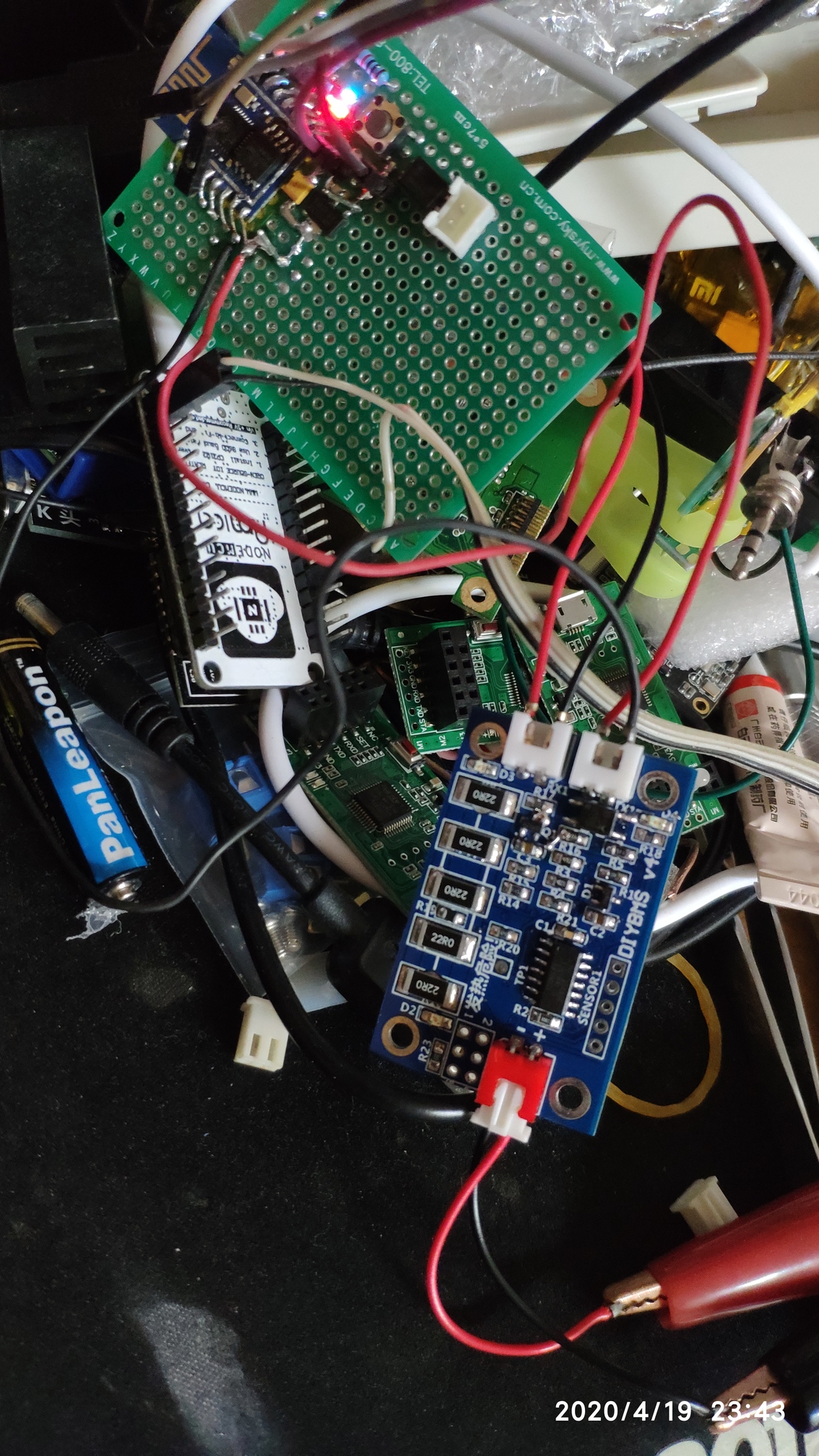
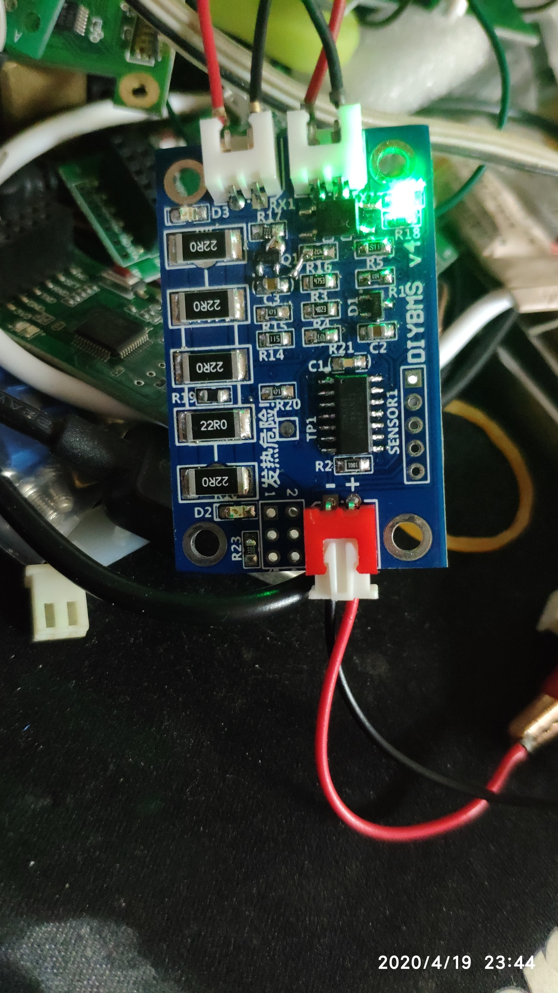
There is 22R resistance in my parts library. I changed the resistance into parallel connection. The total resistance value has not changed. In 4R4.
The program has not been modified!
Does anyone know if JLCPCB is out of stock of AZ432ANTR-E1 or is it that this component isn’t part of their SMT component database? If they’re out of stock, does anyone know if/when they’ll have stock again?
1 Like