Have just ordered 4.21 with assembly from JLC (and controller board) - swapped in part LCSC part number C171461 for the voltage reference as mentioned earlier. Hopefully will work fine - not sure if anyone has feedback on that yet. If not, simple enough to hot air the part off and put on the original part ordered form somewhere else.
Now I just need to find the best place to order the Attiny841 from.
Hi there
Is there any chance to order pre assembled battery module boards by JLCPCB?
I was trying to do it but there are two components that not being selected and they are
ATTINY841-SSU
AZ432ANTR-E1
Thanks
At the moment you can’t get them fully populated by JLCPCB as they don’t have the ATTINY (and possible one other now) component. You will have to order them mostly populated and solder on the ATTINY yourself.
Hi again George, i have again been having a play around with the boards today, so i removed the attiny, the opto coupler, R9/R31, R27/R5, R28/R6 & the voltage reference.
i put the IRLML6244TRPBF from v4 as the octocoupler, replaced the 2.2k from R9/R31 with 1.8k as per v4, replaced the 68k from R27/R5 to 475k as per v4 and also the 27k from R28/R6 to 402k as per V4 and put 2 brand new ATTiny841 and two new voltage references ADR5040 again all from V4
so now basically the board is a V4 x 2 using all the same parts as a V4
i hooked it upto my bench voltage power supply put 3v output to get the device to communticate to the controller, measured the voltage and corrected it in the module page…
turned the voltage upto 3.8… no movement, 4.2 no movement either
ive tested the cableing with v4 board again on the bench power supply and that increases/decreases with what the display shows fine.
i think there is an issue with the traces, its amlost like its not receiving the voltage from the battery, the devices power up fine but the attiny isnt reading any voltage changes what so ever?
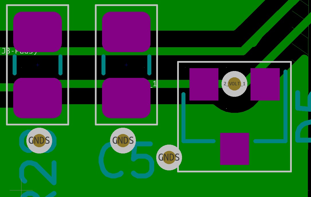
on the voltage ref both the bottom pins are commoned together, then they go to the c2/c5 (c2) and then to r4/r26 (r2) then to aref pin13 and the top pin is grounded…
on the v4 the bottom left goes to the cap c2 then onto r2 then to aref the bottom right is gnd and the top is nothing…
thats the problem, too late to go into the garage to sort it ill look into it tomorrow and report back
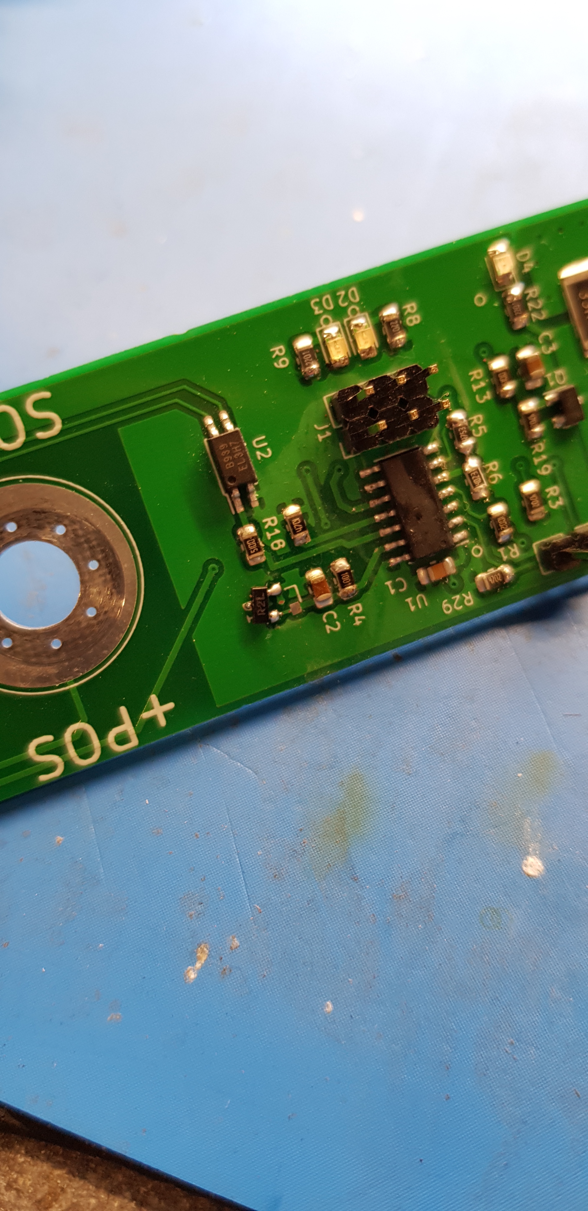
seems so the AZ432ANTR-E1 uses 3 pins soldered and the ADR5040 only uses 2 pins… if i solder it on a angle it should sort my problem, once the AZ432ANTR-E1 arrive in the post ill build it how it is supposed to be
had to solder it on wonky but it works, this is with changing the resistors from 68k to 475k and 27k to 402k works just like the v4 did for now, i will wait for the proper chips to arrive and then compare them together see which responds quicker and more accurate. Thanks stuart and george for all the hard work you have put into creating this
 that £12 has got me 70 of them from ali express