New to your forum and DIY BMS project; have read lots but not ALL the 700+ posts here!
This one caught my eye because my PV storage will use LTO cells, 1.7 to 2.6 VpC usable range (conservatively). Have investigated Batrium and other centralized supervisor BMS. But my bank will be 1000 AHr, NOS pouches @ 55 AHr each in parallel (24S18P layout), so may need more balancing current at some point (more than a couple hundred mA).
Would you think it would work to place a small DC-DC converter to power the microcontroller? I haven’t fully digested your schematic, but I think most of the pins “VCC” would connect after the converter, except of course the dump load transistor Q1 whose drain would go directly to the cell positive terminal via the resistor bank. And the line that monitors the actual cell voltage. I’ve found boost converters that have an input range of 0.8 to 3.3V with an output of 3.3V (search ebay for “DC-DC 1V 1.2V 1.5V 1.8V 2.5V 3V to DC 3.3V Step-UP Boost Power Supply Converter”), for about $1 each. Alternatively Atmel has the ATtiny43U microcontroller with its built-in converter, but its capabilities do not completely match those of the ATtiny841-SSU.
Any comments or suggestions as to whether this should work, or obvious pitfalls?
I also found this on Digikey:
XCL101A301ER-G by Torex Semiconductor
Goes down to 0.9V on the input, adjustable output (3V nominal), capable of supplying 100mA, with 6.3uA quiescent current draw.
This is more expensive at $2.25 apiece @ 25+ pieces.
I agree, changing the cables shouldn’t make a difference. But…
I used the same cables as before : https://www.amazon.co.uk/gp/product/B07SYJ6FST/ref=ppx_yo_dt_b_asin_title_o00_s00?ie=UTF8&psc=1
That are single ended. Joining them makes a double ended. But I assume I had a dry joint somewhere.
As I wanted to shorted these cables after settling on a final position for the packs, I know the final cable length. I only have 3 long ones now, every other cable is the right length.
So, thinking about it, it was either a dry solder joint, or maybe cross talk (Stuart previously discounted this) or something to do with the length. But, as stated I still have at least 2 long cables.
Hi.
Were the board pre-populated with the opto-couplers? Are they the right way around? The pins are not shorted out?
Are the connecting cables wired around the right way?
Simon:
Yes to all your questions is my belief. I teach J-STD-001 soldering, so I am relatively confident of the component placements and soldering. Initially, I did have one board wired in reverse and it did not allow communication. I seem to recall that the chasing leds would skip that board. In both packs the leds chase each other perfectly and I can access data on each cell. It is only when charging that communication is lost. Hopefully I have some time this weekend to investigate and try some new cables. Thanks again for your concern and assistance.
All is well. The problem was with the platformio.ini file. It did have fuses defined but for some reason in my setup I had to hard wire the fuse settings in the upload_flags. Without the lfuse not being set the board was running at snail clock and of course the serial line transmission were bad.
The problem with grabbing code and not understanding the setup leads to long hours… but eventually problem solved
Hi Simon.
It was not a hardware problem but a software one. The lfuse was not being set and the ATTiny was running at a snail clock speed… very odd.
On a positive note I have the diyBMS-LEAF boards running and chatting away. A did the finish assembly on a pair of boards, manufactured a few custom cables and away it went. 2 Leaf cells (2s2P) showed up on the console as 4 batteries. I am still waiting for a few parts but it wont be long now and I will have a pair of 48v batteries (14s) capabile of 3.5kwh each.
I left out the external temperature sensor and not sure whether to put it in but for now I will link the schematic of the current board.
diyBMS-LEAF.pdf (274.5 KB)
@stuart may I make a request? Could you modify the BoM with a breakout of parts needed for controller and 4.2 circuits? Minimize ordering any excess parts. Thanks!
Has any progress been made on adding a Shunt to the controller, I see it was talked about but I can not see any progress.
Would the " LM4040AIM3-2.0/NOPB" be a drop in replacement for D1 “LM4040BIM3-2.0/NOPB” for the reference voltage?
@stuart Thankyou for creating such a great device. i was looking at a way of monitoring my nissan leaf cells over wifi, only devices i could find were bluetooth or stupidly expensive (and also buggy for a finished product)
i have successfully made 28 of the cell monitors
i was wondering if i could attached 2 of the boards to one cell to give it 2A discharge running them in 14s 2p would it work this way?
thanks
also would you mind if i offer a service for brits/europe for premade tested and configured units?, i would send a couple of beer tokens your way per set sold if this is allowed thought id ask first to check 
thanks once again
Hi Gareth, unfortunately this is against the terms of the licence for commercial reselling, but I’m glad you got 28 modules working well.
There is a post further up this list with a redesign including Nissan Leaf cell modules.
Yes although this is an expensive part in the “A” type - perhaps try the “D” variant instead?
That’s difficult as I won’t know how many modules each purchaser would need, so unable to determine the quantities!
I am able to report the diyBMS-Leaf functions as expected. I have a working stack of 7 - Nissan Leaf cells using 7 custom BMS modules.
I have included a link to a video showing stack in operation.
Each module connects to the next in series via a custom 4-pin cable built with very flexible silicon wires. The crimping tool was $12.
https://drive.google.com/file/d/1HWYfil_fstfz0RvEbjMsthRiiVtsacw5/view?usp=sharing
Warning:: it is a huge file, 50+meg.
I added an image as the video is a bit fuzzy.
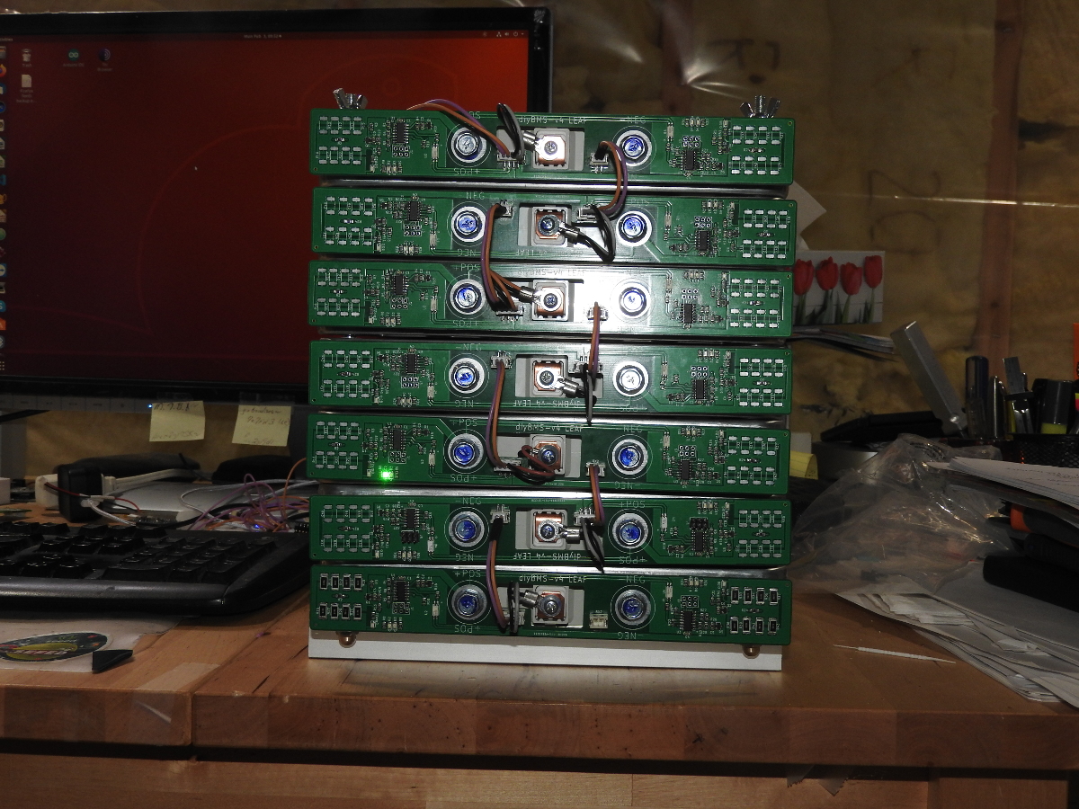
There is still work to be done on the pcb before version 1.00
Yes, this is the solution. Without an internet connection on the ESP boot, the ESP is hanging up.
I’ve connected a mobile WLAN hotspot via Smartphone to the router, so I can usw the DIYBMS now in a off-grid area without internet connection!
I do not have a cable/interface to check the BMS controller report at my powerwall (only in the electronic lab). So I have no reports…
Now, Grafana/Influx is working aswell!
Thanks!
@stuart I wouldn’t expect you to know how much we each need but you do know what is needed per board. Is there a parts list needed for each board on github? Otherwise that would be good to know for the spreadsheet and then we can just multiply as needed.
Thanks!
Yes there is a BOM and CPL files in GITHUB for this purpose.
https://github.com/stuartpittaway/diyBMSv4/blob/Version4.2/Circuit/v4_bom_jlc.csv
Thats to be expected with the current build/code. I’ve had a request to allow the controller to work without connecting to a WIFI hotspot/router for use on a boat, that should be easy enough to do.
This is brilliant, well done.