Thanks! MC3000 on my list if/when completed boards are available. Already use Influx/Grafana/OpenHAB so your BMS is the perfect addition.
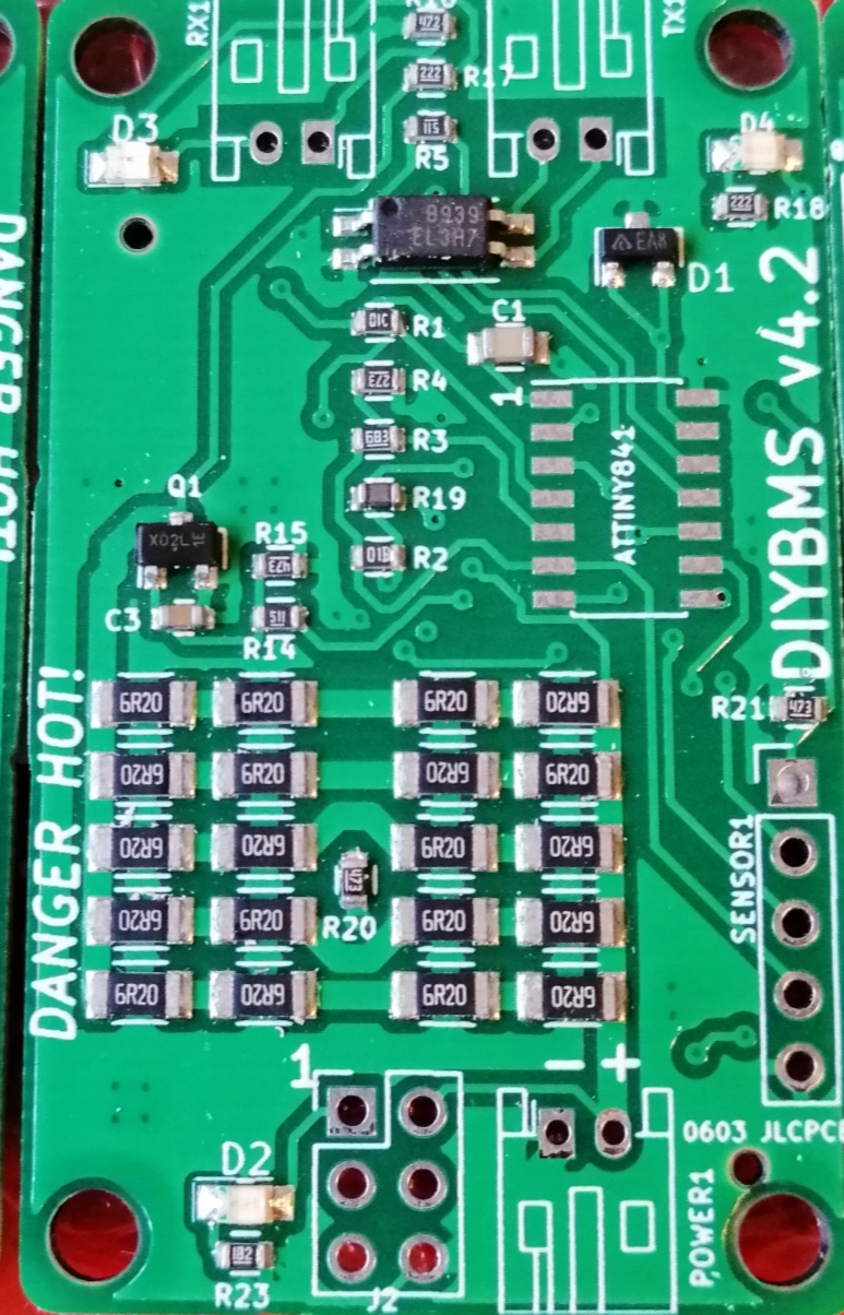
The postman finally arrived with my prototype version 4.2 boards from JLCPCB. I really should be getting commission from them by now everyone else seems to !!
The 4.2 behaves exactly the same as previous 4.X boards except this one is design and price optimised for JLC to assembly build. You don’t need to “upgrade” if you have a v4 or 4.1 board!
The files are here… https://github.com/stuartpittaway/diyBMSv4/commits/Version4.2
Changes are:
- Using higher quanity but cheaper resistors for the load
- Different opto-isolator
- MOSFET is now AO3400A https://www.digikey.co.uk/product-detail/en/alpha-omega-semiconductor-inc/AO3400A/785-1000-1-ND/1855942
- Voltage reference is now changed to 1.25V https://www.mouser.co.uk/ProductDetail/Diodes-Incorporated/AZ432ANTR-E1?qs=sGAEpiMZZMtz8P%2FeuiupSSAVPHlDJwLn0ACymH4zrGY=
- Voltage divider resistor values have changed to match new reference
All you need to hand solder is the ATTINY chip and the 3 JST sockets. The code is exactly the same.
Unfortunately the import tax caught me so these cost £9.25 more than I expected!
6 Likes
Crap, getting drool on my keyboard. I know I can solder most of what isn’t there. The ATTINY will be the only real challenge. The controller still needs to be hand built? I might be able to handle that! Thank you Stuart!!
Five controller PCB ordered. Is the 4.2 zip available? I didn’t see it.
1 Like
Wow. Very impressive!
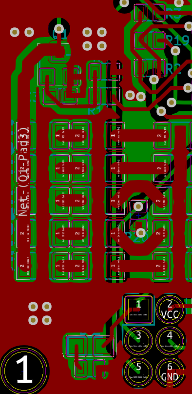
Wait a while for Stuart to reverify the pcb. I mentioned to him about the ground trace, which carries all the discharge current, goes through a very fine trace to pin 6 on ISP connector. It will work as is but this is a weak point on the board layout.
Anything new about your Leaf PCB 
Looking forward to be able to order some of this very nice designed PCBs
Tom, i know this is a little old. I am in the tampa area. Not sure if you have made any progress on building, but I am getting ready to start doing some v4 boards. I have done v2 and v3 boards already. Drop me a line, maybe I can help if you haven’t find an alternative
Well, I sat here and read through all 727 posts to this point
I have 3 questions as i begin down the road of doing the v4 build.
- is the css/js code still stored on the github repo? or is it all local now on the esp?
- if a module is unplugged or bumped ALL modules comm are lost because of the comm loop correct?
- How long can the cables be between modules?
Now it seems i do need to wait to see if 4.2 is ready. Ill be keeping an eye out for the BOM and JLC builds for 4.2
Found answer to number 1. So ill replace that question with this one.
When the controller is getting data. does it do 1 module then report to screen, influxdb, mqtt then move to next? or does it do them all and do a json payload like v2 and v3?
Thanks for reporting this George - I’ve now rectified this flaw and updated the GITHUB repo. The gerber and CPL/BOM files are also updated.
For those following along, the issue was the ground connection from the main power socket over to the MOSFET - this is the new board which now has larger connections across the ground plane to the MOSFET and other parts in general.
1 Like
- All the code is on the ESP - although the controller still needs the internet to work properly as it grabs the time/date from NTP
- Correct if any module fails or is unplugged all comms is lost - this also triggers rules on the controller to take action like shutting down charge/discharge via the relay board.
- As short as possible! The comms between modules is point to point so I’d stick with cables less than 30cm, although you may find longer works okay if using shielded cable.
1 Like
So many questions @CrankyCoder ![]()
The controller asks ALL modules for the data and then updates the screen/mqtt/influx on various timers.
The screen refresh is about 10 seconds, the databases are longer than this about once per minute.
The payload contains all the data in 1 request (per bank as you could have up to 64 modules (4x16)).
You need to add a Wiki entry to GitHub perhaps ![]() .
.
2 Likes
I’ve been following this project for awhile. It’s a great project, thanks stuart. Just wondering if anybody is having trouble with wemos wifi losing connection . I have 2 and both connected to diybms login screen. Now nothing. reprogrammed both. Nothing. I reordered more wemos.
Welcome!
I have found these devices can be very unreliable for Wi-Fi depending on the stack employed. For example, ESPHome can be flaky but Tasmota is rock solid. It can also be the router. In general I have found a dedicated AP on 2.4 MHz can help. I use one of these with OpenWrt.
You should have seen the list before i read through the 700 comment thread lol.
I was just curious if it updated the UI like the batrium does (1 at a time) or if it’s full updates.
soooo we are safe to order boards?
Or is someone updating the JLC stuff too and we should wait?
Im tempted to have JLC populate a bunch of the board. I mean for v2 and v3 I did a diy reflow oven and it worked… but placing those tiny parts was time consuming lol
1 Like
Well it is official … I am brain dead.
I ordered a few of the ESP module boards and a handful of v4 boards assembled sans ATTinty, JST connectors and the voltage reference. All boards are using the HA2801 optocoupler. So I pop the the D1mini on the board and connect through the router and bring up the webpage… It’s magic.it is there. Of course not cell modules but baby steps first… I populate one board with missing components, connect it up and just like magic it appears on the webpage. Will wonders never cease. So put together another board and daisy chain it with the first board and nothing… quess my miracle quota was used up.
Running the second board alone with the controller did not work, It was not seen by the controller. hmmmm fat finger syndrome maybe… Built a 3rd board… same results. Both ‘defective’ boards load code and the watchdog blinks the green led as it should when not connected. When I connect the controller TX to the module RX the watchdog no longer blinks the LED (indication it received something but bad CRC?) and it just sits there like a bump on a log.
I dust off the digital scope (200mhz/2.5Gs/sec) and look at the input wave form at the input to the ATTiny. No noise, clean rise with minimal ringing and when I compare working to none working I can see no signal difference. I have gone through every combination of cables, cells and even tried a different brand of coffee to no avail. The only usable result was I did not like the new coffee and went back to the original brand.
I double checkted the parts against the BOM and looked for board to board differences. I am totally stumped. I am open for suggestions.
HI. I had the same issue charging. Anything more the 1.3Amps charge rate and I would loose conncetion I charge at 15 amps, so no joy. That said they still ballance etc.
After hours and weeks of ignoring it, and returning to it. I replaced all the communications cables (Or re soldered them) and my issues went away.
I did not interfere with the battery connections.
Since I effected this ‘repair’ I’ve not had problems in 3 weeks. And have charged up to 30amp, not issues,
Simon:
That is very interesting as I was having the same issue on two separate independent 16s packs - one 21AH and one 200AH. I used 20 AWG tinned copper wire for the comm and battery cables. I used crimp connectors on all the terminations. Did you crimp and solder each termination or did you solder directly to the boards? I have a difficult time correlating the comms disruption issue with poor connections because I do not see how the traffic or comms would change during charging. I do not doubt your success, just curious. Stuart gave me a line of code to change, but I am at a point where I could try new cables just as easy. The tinned 20 AWG cable was a bit stiff for my liking anyway and I have some 24 AWG that is much more forgiving. Thanks for reporting your success. This is a “must have” for me in order to prevent over-charging.