Engage brain this time - the one on the left !
1 Like
Hey Guys,
Does anyone have the BOM and CPL files for JLCPCB. files that are in the correct format. I am not savy enough to select components, I will for sure get it wrong.
Much appreciated
Hi,
I just finished to update my repository.
Now we have the possibility to order directly from JCLPcb and LCSC in a simple way … I did not test but I hope…
I took the opportunity to update the footprints used on the components in KiCad in order to use only libraries available with KiCad 5.1.5 (except for the Wemos D1 footprint), and now here is what we have:
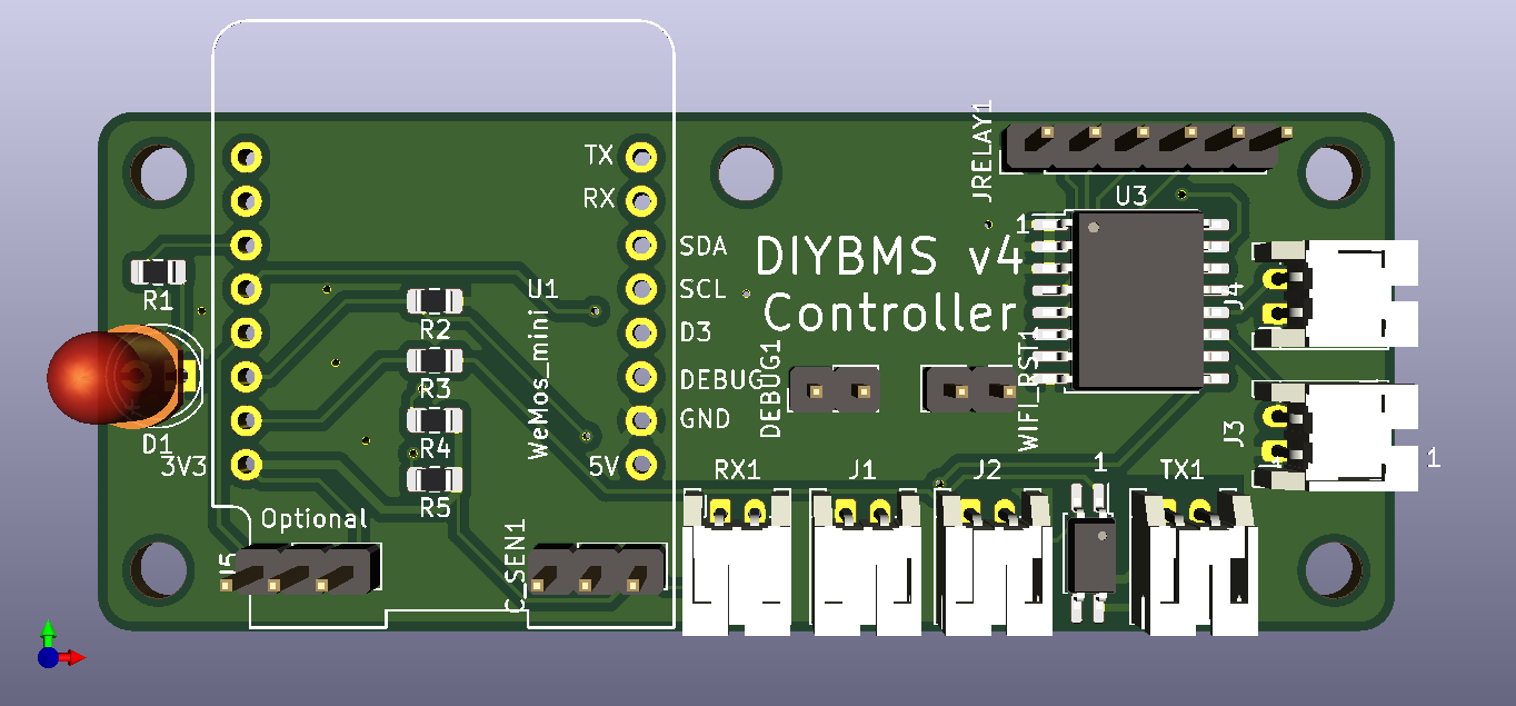
Controller:
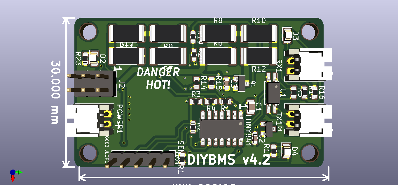
Module:
@rolfbartels
Does anyone have the BOM and CPL files for JLCPCB. files that are in the correct format. I am not savy enough to select components, I will for sure get it wrong.
You can find this in my repository you have a BOM and CPL for each card (1 controller and 1 module) but if you use KiCad and Eeschema BOM Tools, you can generate BOM and CPL for the number of cards desired.
All the material not being available at JLcPcb, Eeschema generates 3 BOMs: one for JLCPcb, one at LCSC and then a last one at Farnell for the module (ATTINY841)
1 Like
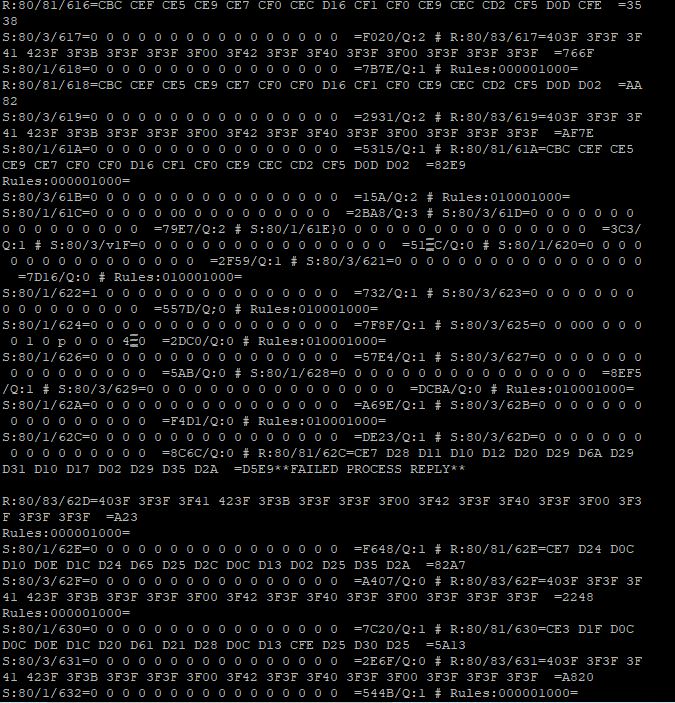
Stuart: Does this log give you any insight to why monitoring stops during charging?
Thanks!
Regards,
Jeff
Is this card that I saw behind the controller and which allows you to control the rest?

Hi all,
I did not find confirmation anywhere, but can we use diyBMSv4 for LIFEPO4 (3.2v) batteries?
A Question - I have built this great project thanks to Stuart for all his hard work (Kiwihacker for the parts), however the boards after programming and power is connected seem to go into power drain mode, blue and red light flashing. Is this a problem with my code upload or a dry solder joint? I will try again tonight to re compile the code and upload again.
I had a similar experience as Troy Dangerfield, after making 14 modules (solder paste and oven method) I uploaded the code to all 14 modules, (Atom/PlatformIO) there was no serial communication. I tested all modules one at a time, same result. then I decided to use the older code I downloaded in December 2019, It worked like a charm…all 14 modules. I latter updated to the latest code, its still working as I type this. Thanks Stuart! this means so much to my off grid project.
,
What code did you use? The blue LED isn’t currently used by the code !!
There is some test code in GITHUB for using just after build and that does drain the cell and test all the LEDs perhaps thats what you have used ?
The suitability of the BMS is for you to determine, I can’t recommend as there are so many different types of battery cells out there.
DIYBMS works down to 1.8v and up to 4.4/4.5V (depending on version). At 1.8v the LED’s will be very dim so it may appear its stopped working, but it does still communicate with the controller.
That looks like it.
Its difficult to diagnose, but it looks like a timeout issue, you are receiving replies from the modules (for instance the line with 62C in it) after we have already timed out and requested another packet.
Take a look at the controller code and find the line
if (receiveProc.commsError> (mysettings.totalNumberOfBanks* 10)) {
change this to
if (receiveProc.commsError> 100) {
and see if that helps narrow down the problem - this may also cause strange behaviour so feel free to put it back to what it was after testing.
Thanks,
I have found the problem! Main problem was me not fully understanding your code and the module, I was using fully charged test battery’s ie 4.2v and the module was wanting to bring it below the 4.1v I have changed this to 4.5v (as suggested above) and was able to get 13 up and running the last 4 have comms errors which look to be a dry joint or over heated part!. So very close to setting up my s14p320 power wall, I am in the final stages of the testing and build.
I have no idea why the blue LED comes on, however it is on all the boards, with your latest code, I will revisit the layout to see if I have an issue.
Could be that you put a blue led in place of the green led?
Good suggestion, however the blue LED is next to the power connector the Green is at the top.
Wierd… Is it on all the time? If it is then maybe it’s just reversed. All led cathode should be left. If you placed the blue led backwards then that could cause that led to be on when the pin(5 I think) is low.
It is not on all the time, just when the red LED is on and some times it just flashes, like when the code is being updated. I will recheck, all the LED’s have the (-) on the left, I used a meter to check the orientation.
Forgive me, my mistake I left some debug code in which flashes the blue led when the PWM code is running on the module (this controls the discharge rate based on temperature).
I know you (stuart) are working on a board we (so many people beyond this site) can get printed complete since not all of us have the soldering skills or equipment to make these boards and I’m definitely looking forward to that. I’ve linked your video on secondlifestorage as well. I’m sure you saw the views climb after my comments. Anyway… does your BMS have support for discharge and capacity testing or should I buy a separate charger for my initial testing before building packs?
1 Like
It doesn’t support capacity testing - better off using a dedicated charger for that.
1 Like