My boards arrived yesterday! They look identical to yours. Man those are TINY parts! I have 25 boards with the same missing parts (assembled), and 5 controller boards (not populated). I ordered the missing parts to complete all boards from Digikey last night. Total for the boards with the SMD assembly was just over $60, and the parts from Digikey are right at $90, including shipping. The Wemos MCU(s) I bought came as a 5 pack for about $15. I did notice that this board design is slightly different that what is in the videos I have seen in that there is no pad for “TP2”, and if I am reading the lists correctly, R19 is the thermistor?
Yes, R19 is the thermistor. Pins 1&2 of Sensor can be used for a second remote thermistor.
I opted to order the boards with the old component for the HMHA2801 and will hand solder it. I found a few viable options on JLC but none had the right footprint (pin spacing was too wide).
30 PCBs assembled came up to $67.46 USD (includes shipping) and the ATTiny841-SSU, HMHA2801 and 2mm spaced sockets from DigiKey came up to $70.36 USD (also includes shipping)… ~$4.59 per board.
Oh and JLC PCB has $7 USD coupons for SMT orders right now!
Okay, so this is likely to be interference causing either comms issues or the ESP8266 module to have problems.
- Does the ESP8266 still work during charging - can you get to the web pages okay?
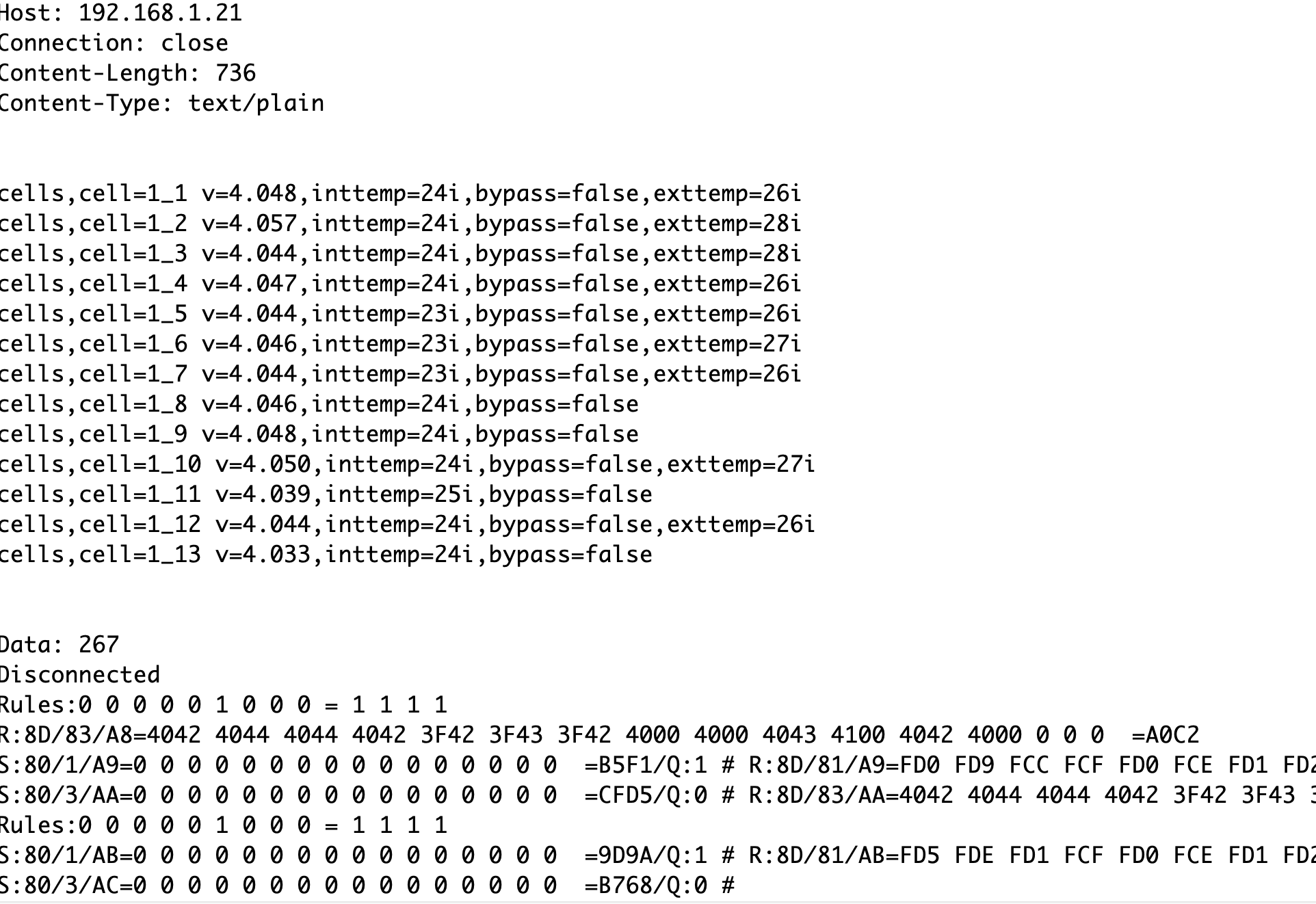
- Can you take a look at the serial output on the debug pins (connect to this using an FT232 type cable)
- Can you see some of the green leds on the modules “chasing” down the comms path? Does it always stop at a certain point?
- How are you powering the ESP module?
- Does the ESP8266 still work during charging - can you get to the web pages okay? Yes, I can access the controller and move from page to page. It has communication error highlighted on rules.
- Can you take a look at the serial output on the debug pins (connect to this using an FT232 type cable) Not experienced with this, but will research some youtube videos and make a cable if necessary.
- Can you see some of the green leds on the modules “chasing” down the comms path? Does it always stop at a certain point? Yes, the slightly delayed pair of chasing lights travel from cell 0 to cell 15 without missing any boards. They do not stop or miss any board.
- How are you powering the ESP module? I am using a standard cell phone charger. I connected the charger connected to the ESP and the charger connected to the battery bank to different house circuits with no change. I also tried disconnecting power to the ESP during charging and reconnecting with no change.
[/quote]
Thanks for the update @malabarmcgyver looks like the comms is working if you get the chasing lights.
Next step - get a debug cable working, you just need a serial to usb adapter of some sort - perhaps you have one for programming an arduino?
I’m getting comm error and only way to recover is reboot controller.
My scenario: charging at 40 amps on PV, and building external temp sensors (about 5" long). Looks like I can only put one every other cell before the comm error starts again. Could this be a timing issue when adding the external temp sensors?
If I just connect the external temp, seems to be okay, when I push into the battery pack (some pressure on thermistor), comm error.
Comm error again, removed external at pos #0, seems normal now. I have only 5 connected.
Disconnected all externals, waiting for comm error.
Well, looks like I have a comm error without the temp sensors.
Sounds like this could be a coding issue to me. Do you have the ability to get the debug serial port logs?
I need to start over, just found a bad module. Evidently when I moved the modules around when plugging in the external temps, I caused a module to short either the TX or RX, the pins are really sharp and scratched through on a cell to cause short.
Red light always on. Another burned the trace from RX pin. So, I clipped all pins flush with boards and put tape/insulation on the backs.
Now to build another module. Think I will test the external temps again, while I have the time.
UPDATE: All good, 9 external temps up immediately on connecting, now to build 5 more.
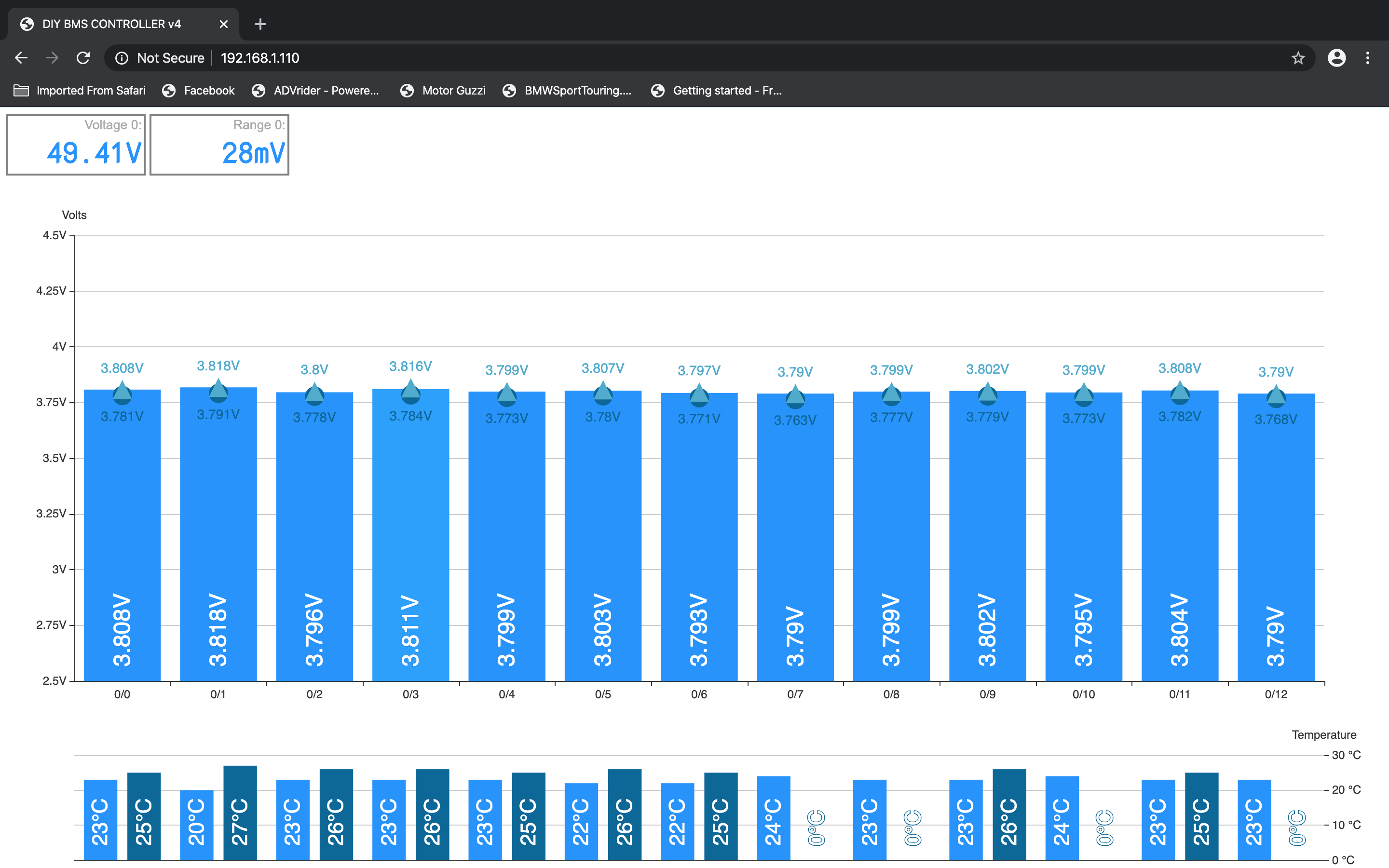
I probably need to move over to surface mount connectors to avoid the pin through parts.
Hello @malabarmcgyver, I am using this for debugging:
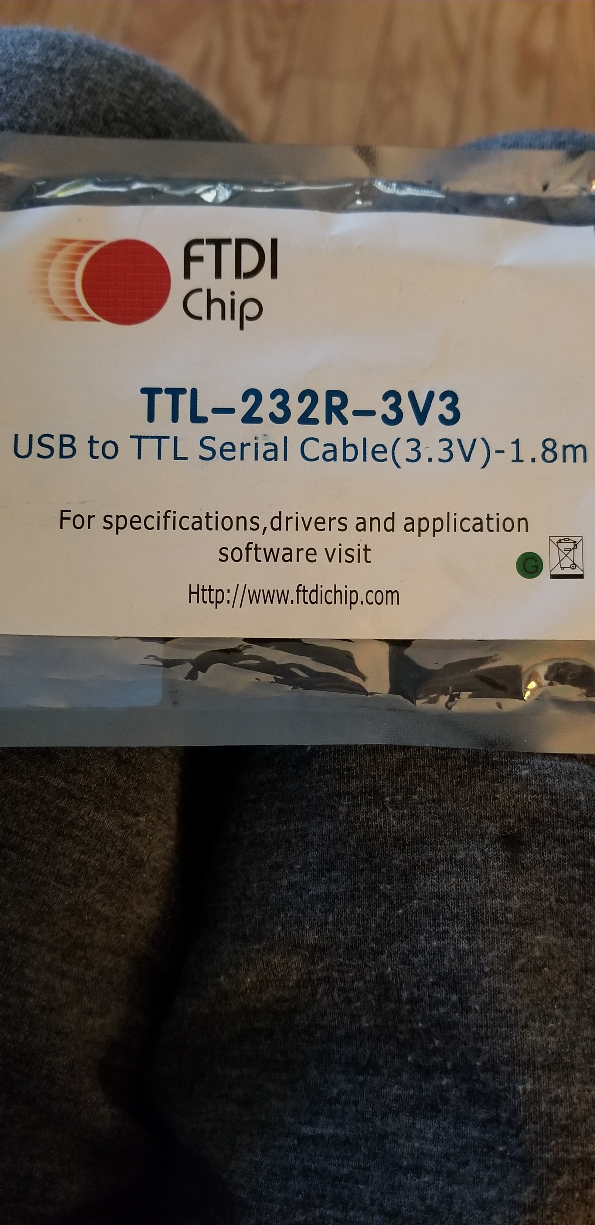
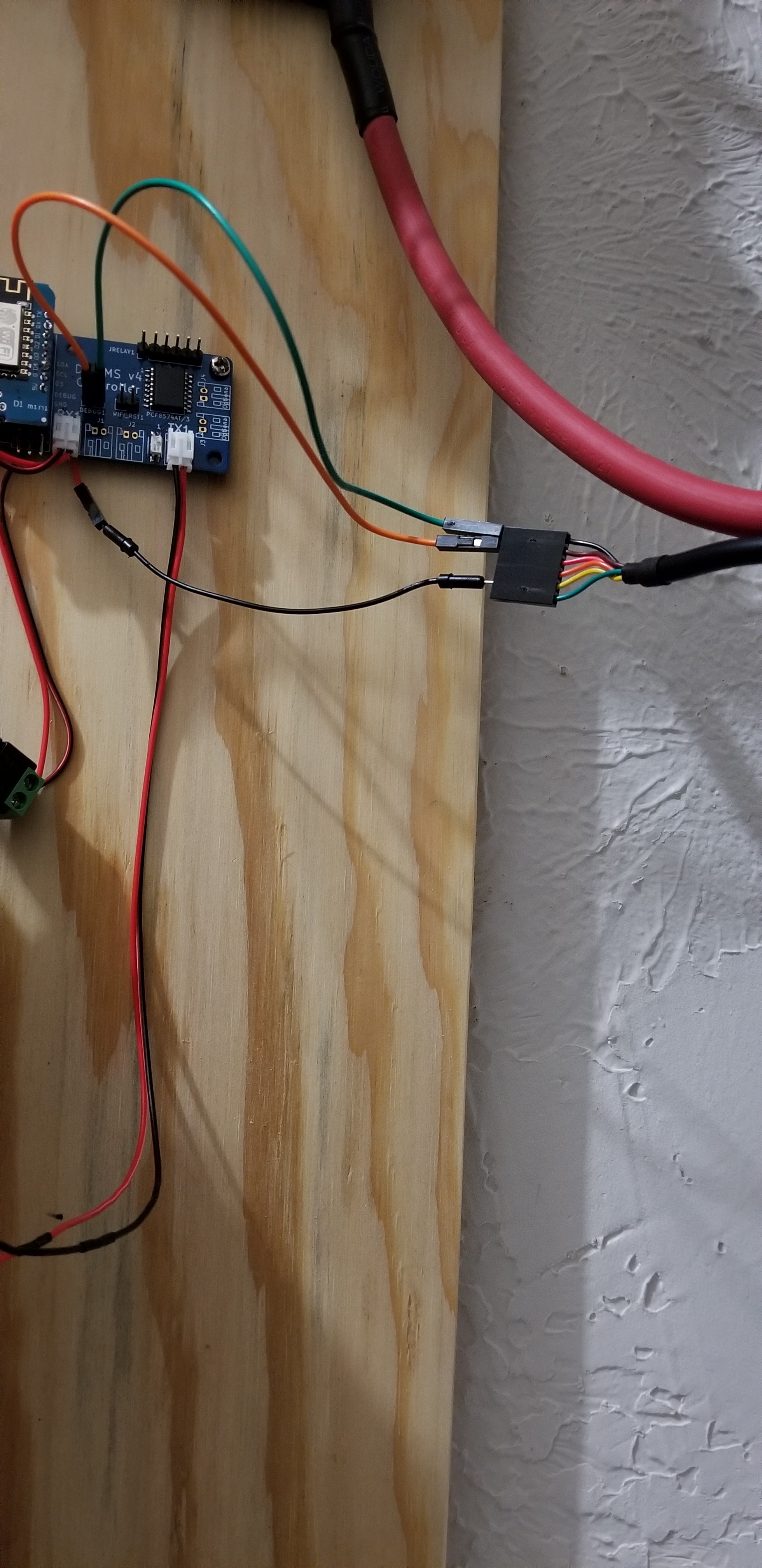
I’m on a MacBook pro, I must connect USB port first then connect the wires at the Controller board. Green jumper is ground, Orange jumper is clear to send, Black is D4 on esp8266.
Thanks David! I appreciate the advice.
The only concern with going to SMT for the connectors will be in the long term durability of the connection to the PCB. If you don’t unplug/replug the boards often it may not be a major concern though.
I don’t have a problem with them now, just clip them after soldering and tape. They do get a lot of jostling plugging and unplugging the wires, at first anyway.
Is there a source for jumper wires that are good for these boards? I see a lot of red and black with only one side crimped. Any help is appreciated!
They are available online but often in lengths that are not ideal. The cables can be built without too much hassle using the crimp connectors though.
Or get the ones with wires connected, and a few mins with a soldering iron and heat shrink, and away you go.
There shouldn’t be any need for the clear to send cable - is this MacBook specific?
Normally connecting the 2 debug pins to ground and RX (receive) pin on the TTL breakout board should be enough.
Baudrate is 115200 baud (8N1)
I’ve used these, you will need to swap the pins on the cables, mine were cross over rather than straight through.
That is the pinout on the cable (cts) brown pin #2. Don’t think mac specific.