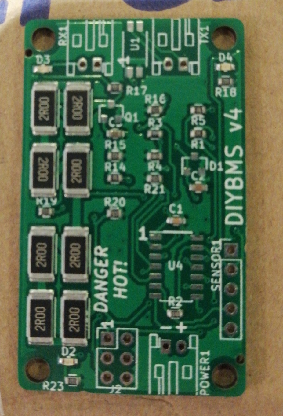
@Tiger_One you should see the green lights of the module chase along from one module to another.
Where does the “chase” stop? Thats the problem module.
@Tiger_One you should see the green lights of the module chase along from one module to another.
Where does the “chase” stop? Thats the problem module.
Okay, I think they kept going all the way through like normal, not sure of that. They are normal now with 2nd controller board.
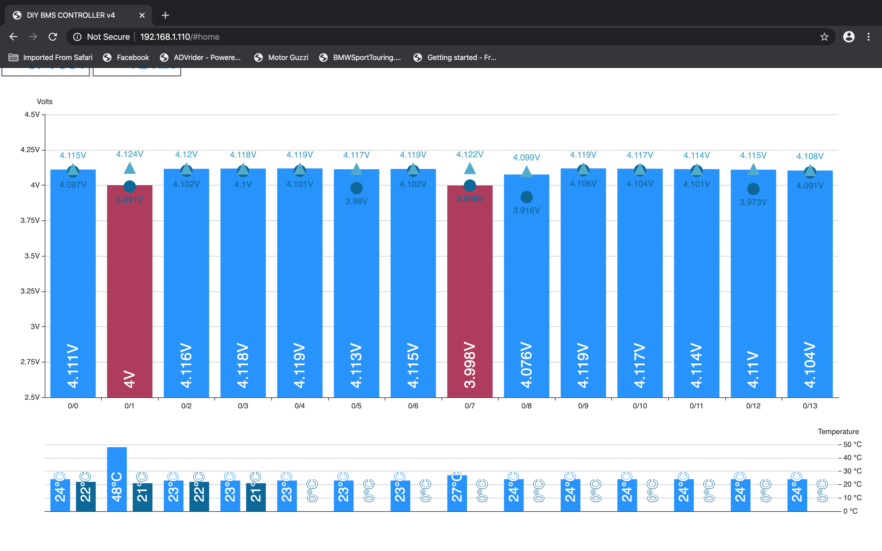
After plugging in 1 external thermistor in cell #0 lost communication. Green lights running through, BUT, #0 starts over before the last half of cell bank finishes.
I’m still testing, trying to bring up one at a time. Appears that the controller board is at fault.
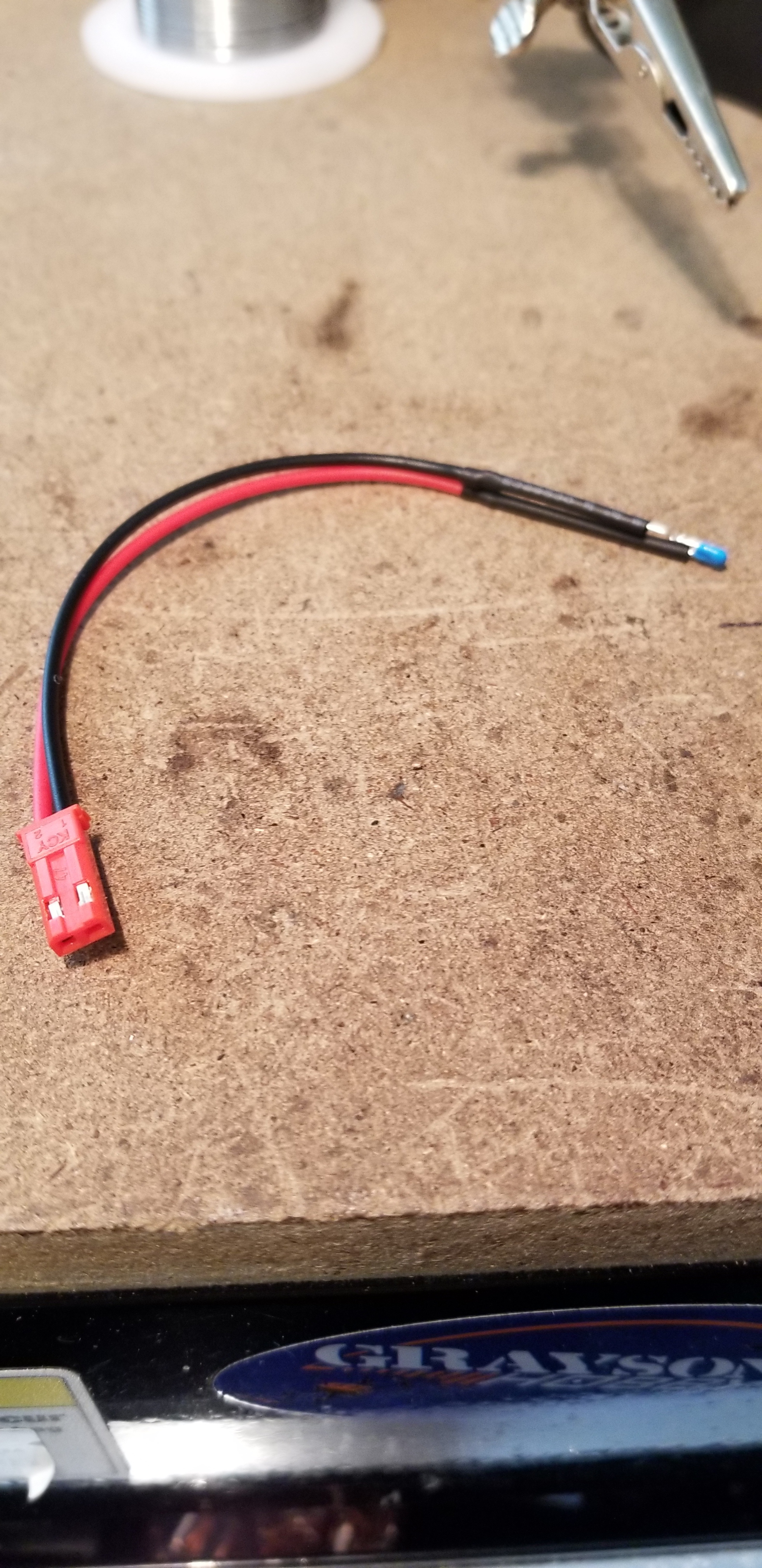
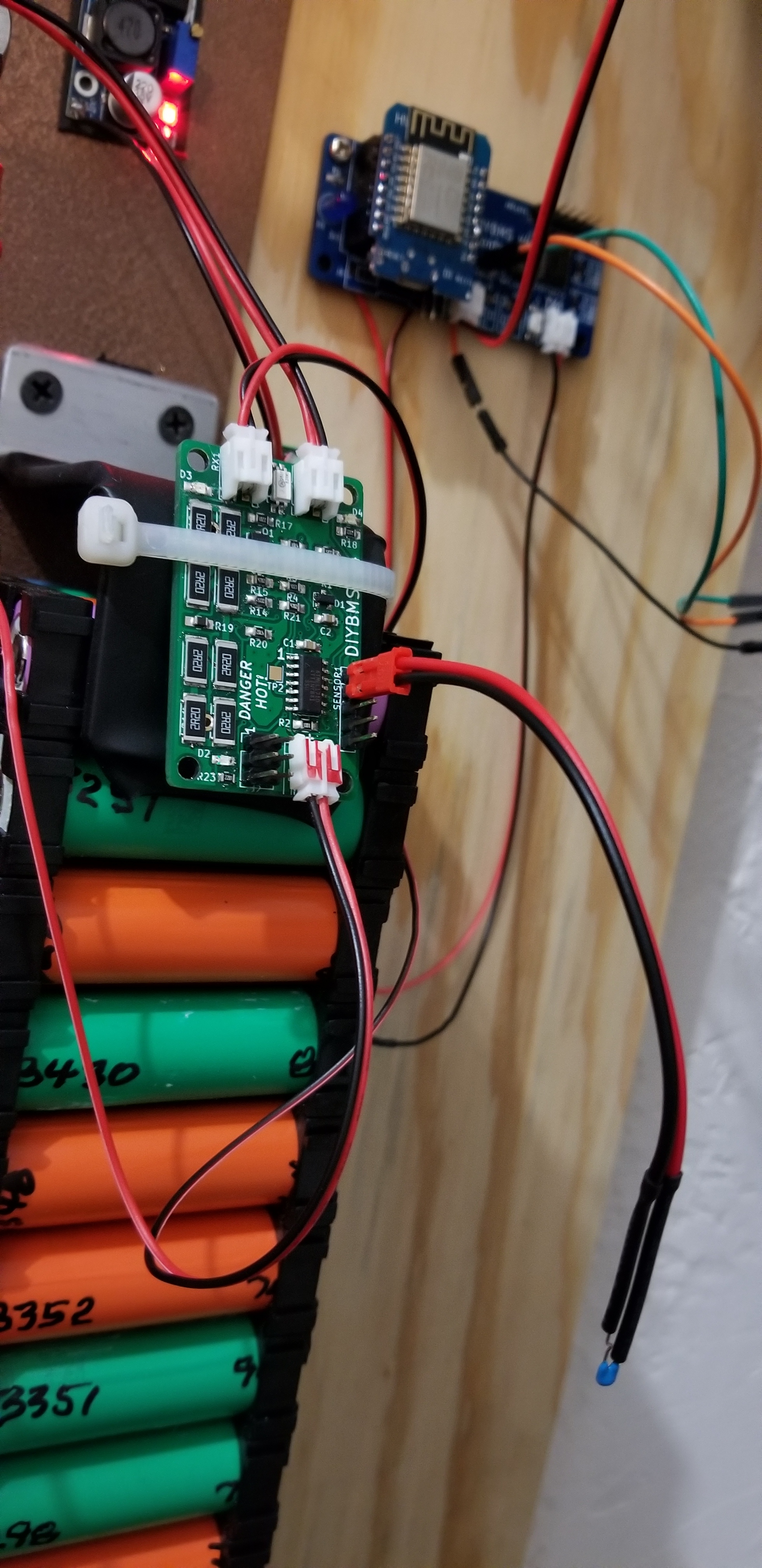
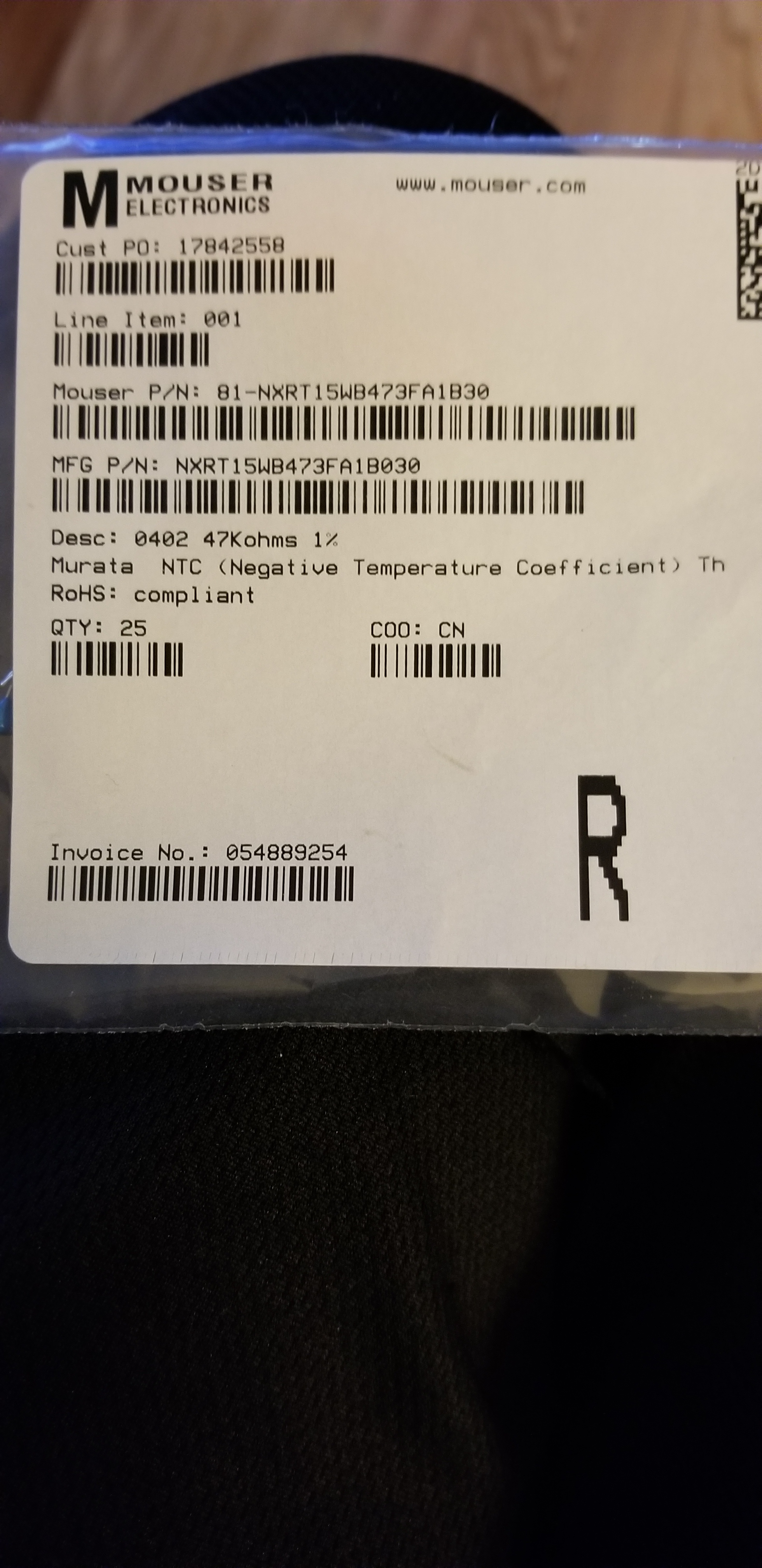
Pics of the thermistor:
Okay, after much thrashing about, making a 3’ jumper to walk through the modules (doesn’t work, too long?)(turned out to be bad solder joint). I was able to determine the second module is not working??? Controller is fine.
So, one of those external sensors is bad, maybe shorted, I will test them.
Reconnect supposedly bad module, works fine. All thermistors are okay. I am at lost to explain what is at fault.
Maybe the external sensor is throwing off the comm?
Nope! Started connecting them again, from #0 to #3 all working fine. Will continue building.
Only having a couple components to solder isn’t too bad really, that new assembled board looks great. Can’t wait to see how it tests out and then I’ll order the 30 I was planning to order.
I’d suggest a very careful search, with inspection light and magnifying glass, for a dry joint and a whisker of solder bridging between tracks.
Then check everything you’ve discounted as being impossible.
Don’t forget that there isn’t anything special about each module, so you can unplug them and put them back in a different order to see if the problem moves.
Looks good so far, first module up and running.
I’ve tweaked the resistor value for the blue led as its quite dim
I’ve also swapped the optoisolator from HMHA2801 to HMHA2801AR2 they should be very similar, but I’ve not tested that yet so if you are planning to order, might be worth handsoldering these.
Also swapped over LM4040B to LM4040A20IDBZR as this is available through the JLC assembly but the price is very high, so again exclude and handsolder using parts from elsewhere. Its the trade off of cheap assembly against availability of parts.
Even with handsoldering, only took 5 minutes to complete the board so happy with that.
Looking at their parts list they don’t have C127070 in stock but do have C48833 and its about 1/4 the price. Not sure it is a drop in replacement though.
I’ll hold off on ordering for now as I’d like to get your updates before ordering, I saw the schematic has been updated on GitHub but not the CPL/BOM (yet?)
Yes the CPL generation file has gone wild and put the components all over the place!
Very likely another bug in the plugin… I see another PR for the plugin to add DFN component rotation (I don’t think you are using this today so maybe not needed)
Will be possible to make 3s or 4s hardware configuration in one PCB instead Attiny841-SSU using Atmega328p-AU with higher I/O pins to avoid using 3 or 4 pieces of DIYBMS v4 ?
No, that would be a completely different design. Keeping the electrical seperation is the key part.
I generated a new BOM/CPL from my clone of your latest jlc branch code and it seemed to place the components correctly but I did notice that the cost for 30 boards (max they allow) went up by ~$25 USD compared to the “master” branch (IRLML6244TRPBF was not picked for placement so that could explain the price difference).
How has your testing on the updated “pre-assembled” PCBs been?
The 16S is working fine - Thanks Stuart!
Now, I am seeing loss of communication when charging. The controller stops communicating and the leds flash twice in about a second instead of once. Will someone explain what I have done wrong?
Thanks.
Regards,
Jeff
Hi Jeff, the double flash is a fail safe on the modules, they will still balance but go into that mode when there is a prolonged comms issue.
How are you charging? What length of cable do you have between modules?
Hi @atanisoft I’ve just uploaded a full set of Gerbers and BOM/CPL files - the placement looks good on these.
Note that I’ve selected some replacement parts
The cost for assembly at the moment and all the part (excludes ATTINY841) is $73 USD for 30, so less than $2.50 USD per board.
NOTE I’VE NOT TESTED THESE NEW COMPONENTS SO YOU DO SO AT YOUR OWN RISK/COST - IF UNSURE, EXCLUDE THEM FROM ASSEMBLY AND USE THE OLD PARTS.
https://github.com/stuartpittaway/diyBMSv4/tree/jlcpcb_assembly
Edited: Also changed resistors in voltage divider to basic parts, so this reduces the cost to $67 USD so $2.23 USD per board
That isn’t too bad, add in the ATTiny and the overall cost for a 30 pack of boards will be ~$100 USD (approx $1USD per ATTiny from Mouser or DigiKey).
from a review of the datasheets they appear to be a drop in replacement with the ADR5040 having slightly tighter tolerances for the output voltage but otherwise functionally identical. Definitely worth a test though.
From the datasheet of HMHA2801 it appears to be a not recommended for new designs, perhaps swapping for the FOD817 would work and not have the concern of the HMHA2801A?
I have a 16s LiFePO4 58.4, 25 amp charger and it runs at about 27 amps. The issue begins immediately at charging and ends when charging stopped. The 200ah cells are back to back and the daisy chain cables (16 awg) are approximately 15 cm. The controller TX and RX are about a meter each. Thanks for your concern and attention.
I re-read this entire blog and I noticed two posts with similar issues. One with charging and one with discharging at high rates.