Hi @stuart,
I have reported previously that I have problem with 20 modules, not being read all the time.
Manifestation is that after ESP is restarted, it scans ok, reads ok several times, but after some time it does not fetch data from bank1.
I have captured logs and reported issue on git:
I am not sure if there is something more I could get to support you with this.
If you see something I could do - please say.
Thank you for support.
(I will try to investigate console logs for case “I turn on battery charger and monitoring stops”).
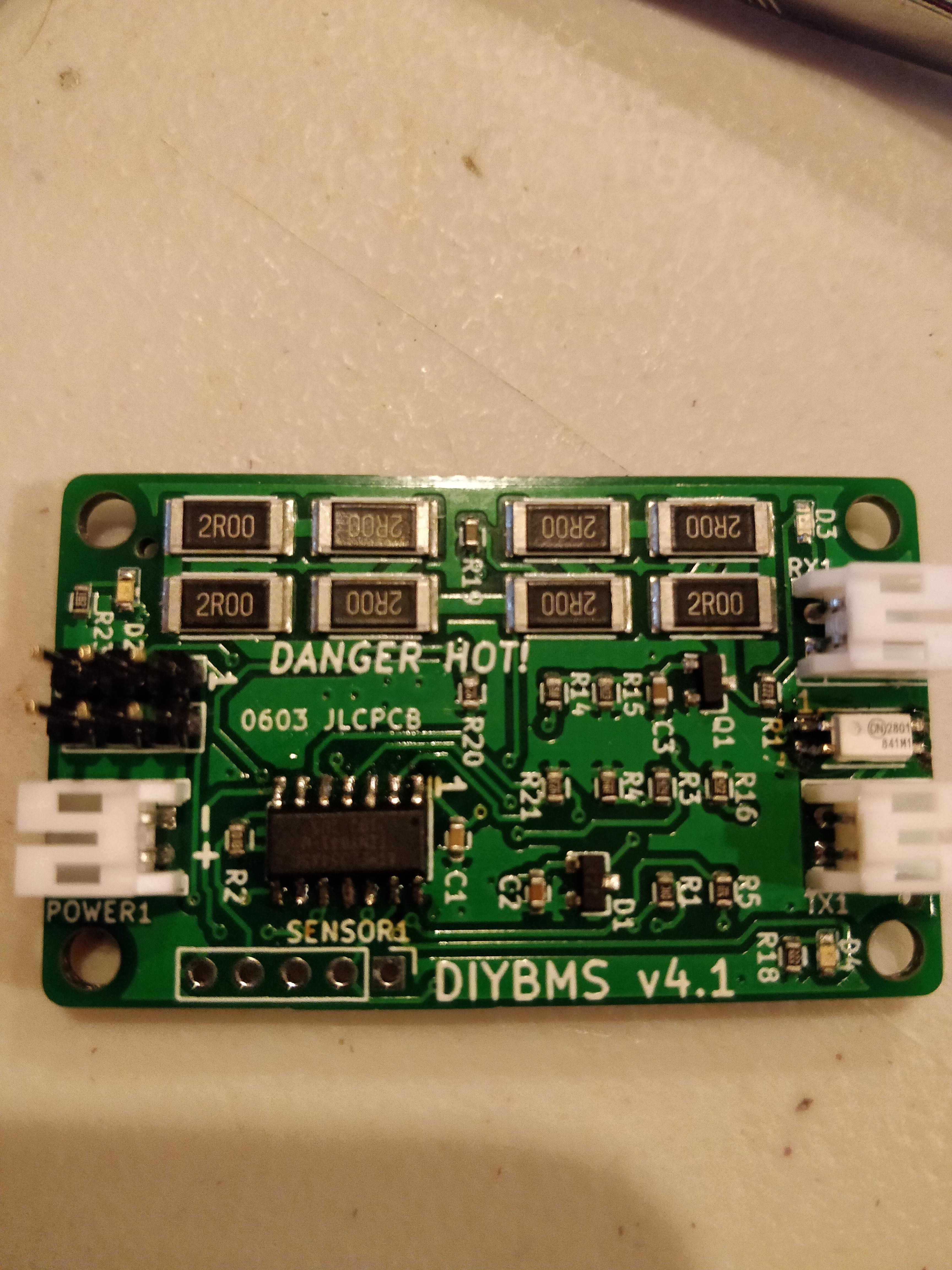
Overall the quality looks pretty decent and soldering the ATTiny wasn’t that bad with a 75W iron (900M-T-B tip, wish I had a smaller one!), flux pen and 0.025" solder.
Now to fight with the USB ASP device on Gentoo Linux, it doesn’t seem to be showing up for some reason when plugged in. Once I solve that I will flash this and do some basic sanity testing.
Before you connect the battery just do a simple multimeter continuity test between positive and negative pins on the module to check for dead shorts.
There is also a test sketch program in the code you can use which will test the LEDs and load resistors, don’t leave it running for long as it will drain the battery!
Will do, I still need to assemble the packs so will wire up a couple cells in parallel as a quick test setup. I have about 200 cells left to capacity test and another ~650 that will be shipping tomorrow and they should be here in about a week and the capacity testing will continue. I will have at least one 7s80p pack online for testing by end of the month and once the new batch of batteries have been tested it will be another 7s80p pack to put in parallel.
Good to know, you can also expect a PR to fix up a couple issues with the platformio.ini file related to fuses as the latest version of PIO no longer accepts them as part of upload flags.
On that note, from PIO is it as simple as running the “Upload using Programmer and Set Fuses” option to have it burn both the bootloader and the code or do I need to run avrdude manually?
I’ve recently been updating PCB for the modules (v4.2) technically they work the same as v4.0 however I’m trying to make them as simple and cheap to assemble as possible using the excellent JLCPCB assembly service.
To aid that, I’ve moved to using the TCLT1003 optoisolator
At the moment I DO NOT recommend using the branch jlcpcb_assembly - its still in development - so stick with the master branch and v4.0 boards for now.
In quantites of 30 boards, assembled (excluding ATTINY) the cost is $2.21 USD per board - about £1.65 GBP.
The ATTINY841 from Digikey UK is £0.77 - so the whole board costs about £2.50 once complete.
Perfect, I was able to sort out the USBASP problems on Linux by adding the udev config file and restarting udevd. I was able to flash the test program and the actual program. I just need to sort out how to read Serial1 output from the board, it looked like it is routed to the 6pin header so I think I should be able to connect a few jumper wires to connect it to the FTDI cable I have.
The only reason I’m interested in that output is from the test program at this point. The controller is not ready for testing and I won’t be able to hook up the modules to each other yet since I don’t have the crimp on connectors (skipped ordering them with the rest of the parts as I had some on hand but they are too big). I should have them on hand next week though. Until then I will do some tests with the modules as-is to ensure they at least power up and are mostly functional.
Also keep in mind I will be using an esp32 for the controller rather than the ESP8266, more on that later though…
EDIT: tested all seven assembled modules with the test program and they all appear to be acting normal. Will test further once the crimp connectors arrive next week.
I was exploring using C29981 as another option. From the datasheet it is very similar to the previous part and it is slightly cheaper than C118296 with similar specs. Thoughts?
GeorgeBoudreau great job on the diyBMSv4-Leaf, have you forked this design on Git and is that something you are willing to share?
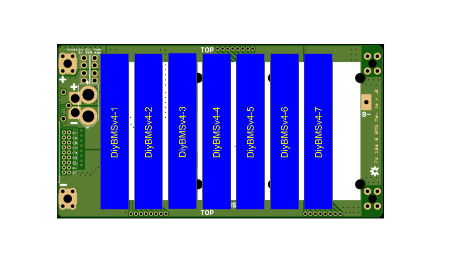
Stuart and others - dragging up an old post from Edoardo_Conti, I am also interested in creating a Jehu compatible BMS “diyBMSv4-Jehu” lets call it, that would allow me to stack a single (165mm x 88mm) PWB with 7 diyBMSv4 PWB segments side-by-side and then use the 16pin IDC connector to link each single stacked cell to each diyBMSv4 portion of the circuit. This would essentially replace his Walfront 24v 7s BMS. Other than current limitations can you think of any other limitations that I need to be aware of?
Be VERY careful with those PCBs. The PCB traces near the IDC connector pins are setup as “fuses” and can cause the BMS not to see that there is a problem cell on a PCB in the stack. This is one of the reasons that I will not be using the stack of these PCBs that I have on hand.
I have both of these parts in my parts bin so I tried out the TCLT1003 and it worked fine (has has been for 24 hours now) I’ve also tested it at various voltage levels between 1.8V and 4.5V and it didn’t drop comms.
This is more of a general problem with the Jehu PCBs, I like the idea of them but there are a few critical issues with them (and similarly created PCBs). The biggest is the trace “fuse” on the BMS sense lines, this is a problem mostly in the event that one of them burns then the BMS will not see the failed cell/fuse and it won’t know or be able to disconnect the broken PCB from the “pack”. Ideally the PCB should be designed as parallel cells with fuses between the cells and the “bus” so that one PCB can be dropped from the pack easily and safely if/when there is an anomaly on the PCB.
However, if you do adapt diyBMS to the Jehu PCBs, I would highly suggest bridging the “fuse” on the PCBs and using multiple smaller stacks of the PCBs in parallel so diyBMS can drop a stack quickly if there is a problem on one of the PCBs in the stack. I would also highly suggest the external thermistors to monitor each PCB for any heat and disconnect when over heating.
Very nice! One other benefit of C29981 is that it is a “basic” part. Another option is something like the 6N137 which I’ve used for DCC signal decoding, the only thing that I can see different on that is inverted signal which can be easily sorted on the Serial side.