If you haven’t built the devices yet - I’d strongly recommend building V4 - its much better!
@stuart Unfortunately i have built the V3 before V4 was out. Now i have 5 modules not working correctly i am thinking from poor components and soldering. You suggested getting JLC to build the board for me after i was going to try and make the board through holes instead.
However now JLC want a CPL file as well as the gerber and BOM. Didnt even know what one was until today.
Thanks
Andy
Hi Stuart
First I want to thank you for the big and fine job you have done with both V3 & V4 of the diyBMS
I have a question
Have you considered to make a Current sensor ala., the Batrium one, that can be connected to the isolated RS232-bus?
The circuit can be based on a current shunt, like the Batrium one, a AMC1301, supplied by a SN6501 with voltage-regulator on secondary, and a Attiny841 as the rest of the modules.
Br Steen
Yes I’ve considered it (take a look at the earlier posts) but not built one yet. There is a spare analogue port on the ESP module to allow this.
I 2nd the current sensor motion. I watch mine on an app supplied with my Sol-Ark (charger/inverter) and also the Sol-Ark has an LCD monitor.
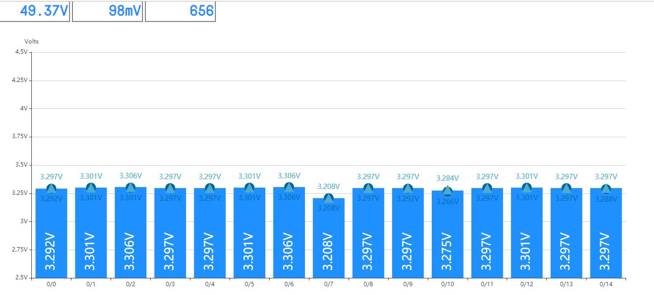
My pack balanced last night, it is 22mv, amazing system.
Let me know if I can give you a hand with the drawing of circuit, or PCB layout
Maybe consider to be able to add at least 2 currents sensors. One for input to batteries, and one for output from batteries
Br Steen
I’m planning to do the same creating a bolt on for Leaf batteries
Do you plan to make a design like the LeafMon with small compact PCB’s and a “Mother” PCB to hold the active smaller PCB’s
I will be doing up a diyBMSv4-Leaf pcb with 2 diyBMSv4 modules that will bolt directly on a Leaf cell. it will have on RXin (2pin JST) and a 4pin JST with the common supply lines and TXout to the next in line cell. If you look at the Batrium Leafmon it will have a similar layout but containg Stuart’s hardware and work with his ESP hardware/software. There are a few hardware changes such as no external high power resistor and the 2512 power resistor bank has been reworked for the layout. When all is done I will offer the files Stuart for inclusion in hit git repository.
I do not have a “fixed version”. The MFG did the correction. I was wrong in stating that the diodes were incorrect, there was a question on them, but the file has them correct. It appeared that there was a missing part, but that is not correct. Specifically D1 is in the build sheet, and it is on the BOM. but the part was not in stock, so I will not have that part populated on my boards when I get them.
Basically there is one part that did not line up correctly (Q1 was upside down), and one part (D1) that is missing (out of stock) in my build.
Yes the 15S issue is resolved, but you will need to download, compile and flash to the controller and all modules. Sorry!
would be great if somebody could contribute providing precompiled binaries.
rgds
Thanks Stuart! I just wasn’t sure based on Marko’s response.

Nice work @GeorgeBoudreau!
Take a look at the jlcpcb branch in GitHub, I’m going to try and tweak some of the parts to make them work with the jlcpcb standard parts list.
The 2r2 resistor for instance can be dropped to 2r0.
@GeorgeBoudreau forgot to ask, how do the two halves of the circuit work? Is the leaf cell split into 2?
Looking good 
Do you use the JST PH conenctors for connecion to the middle terminal of the battery?
These LEAF batteries are 500w from new, which gives 250W pr battery
A few connected in parallel gives a quite big charge.
Will 1A be enough for balancing?
These JST PH connectors are rated for max 2A.
Have you considered a connector rated for higher current if higher balancing current is nessesary?
Br
Steen
The Nissan Leaf modules are 2S2P with a common tap. Between the 6mm connection points is the 2S. For balancing I use 2 diyBMSv4 circuits on a single board. If I did use separate boards I would hardwire the gnd of GND of one board with the VCC of the 2nd board and connect them to the ‘center tap’.
My arrangement will be 14S or 7 cells for 48v batteries. I currently have enough for 2 batteries with the same capacity. Although 1/2 of a module is 250w that is for new units. Unless you are buying a new Nissan Leaf and ripping out the battery module you will end up with cells with less capacity. While 1amp seems low you usually trying to correct small imbalances over time. I have limited my load to slightly over 1A.
I agree a higher discharge current would require a JST change. Connector size is an issue as well as resistor dissapation, I do not want to change the board size as it currently fits the width of the Leaf module.
George
I have a problem. Was making external 47kohm thermistors and plugging in. When I got to the 3rd or 4th one, lost communication with the modules. Removed all external sensors, still no communication after several reboots???
Looking at debug, no "R"s, sending but not receiving.
Changed controller board, used same WEMOS, working okay. I will start connection external temp sensors and see if the problem returns.