Sure they can. You connect them to a CMOS multiplexer, then you can measure the resistance of each one separately.
interesting, tell me more.
I never heard about Multiplexer.
I googled it now and found some more info, but I have no idea how to monitor up to 64 pcs.
I just found another project:
64 to 8 or 1 Analog Digital Multiplexer Switch
I 've seen now, that this seems to be a commercial project, and it seems that this is no longer available on aliexpress…
But that means I have to build something external other to use it with the DIY BMS.
My original idea was to add something to the mainboard of the DIY, or maybe to add or connect a extension board (for each pack) to the DIY BMS
Well, the veritable 4051 (available e.g. as MC14051B) does basic analog 8:1 multiplexing. If you connect its Enable inputs to another 4051 you need nine of them, six digital outputs (either on the MCU, or an I²C peripheral), and an ADC converter (ditto).
That means the MC14051B is just an analog multiplexer right ?
I just want to go directly to an I2C bus with no converters (or ADS).
Converters (or ADS) means more things to monitor, more power consumption and more possible errors.
Any Idea how to solve this directly with an I2C Bus ?
Well, you could use the P3T1755. That’s an I²C temperature sensor that can be set to one of 32 addresses by clever external wiring of its three addressing pins, so you only need two buses. (They could have gone to 64 … oh well.)
@stuart
i have the v4.4 controller with 16 v4.4 modules it was running Firmware_2023-02-21-08-55 two weeks ago and had no restarts for over 250 days this firmware was rocksolid.
now i have updated to Firmware_2023-12-27-12-02 and i have wifi connection issues it disconnects sometimes then i have to reload the browser page. (this is not the problem)
today i had a crash. after 10 days running the controller crashed and rebooted, but i lost power at my house because the canbus is needed for my sunny island.
this is not critical unles i am doing some firmwareupdates on my hardware, but its anoying.
as far as i know i cant use the older firmware again because i want change to v4.9 all in one.
Hi @voltmeter this seems to be a regular complaint about WIFI issues - which ultimately cause the ESP to restart. I believe its caused by the underlying core ESP libraries, but I can’t accurately pin point the root cause. Some people have no issue whatsoever.
A few things:
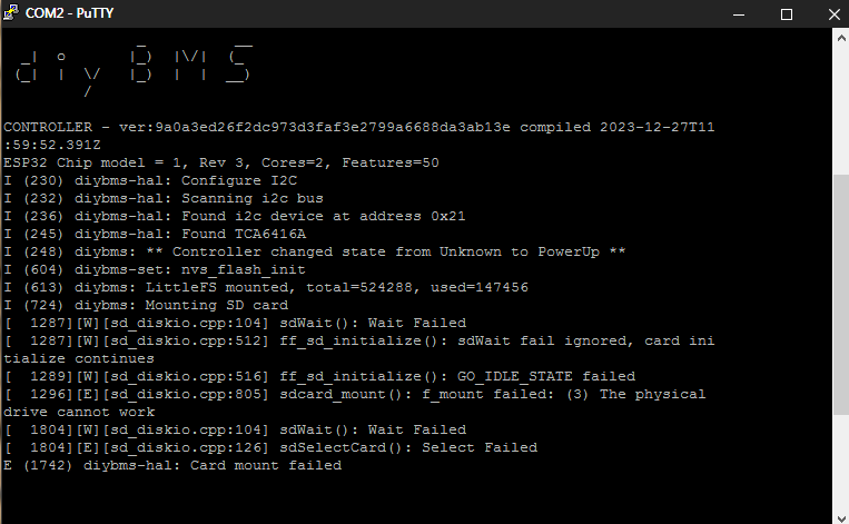
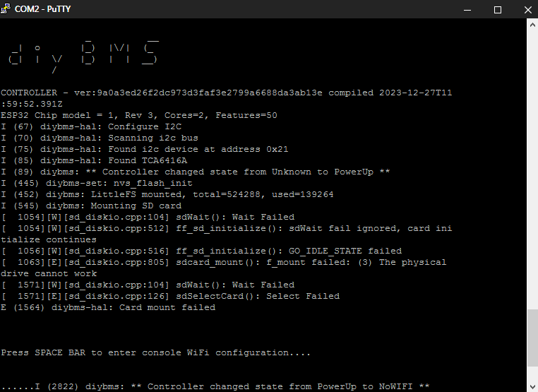
- Can you check what version of the ESP32 you are using (look at the output on USB Serial when the ESP is powered on). Some hardware revisions of the ESP appear worse than others.
- Ensure the 5V power supply can supply 2Amp+ current
- Do you have an SD Card installed? If so, remove it and see if the problem goes away.
- Is the WIFI signal strength good? The ESP can struggle if not.
yes i have a sd card installed. i take it out and test again
wifi signal is strong, the 5v supply too (15W meanwell)
no way
with this new firmware the controller reboots instantly if i disconnect my wifi.
have tested this with v4,4 v4,5 controller with different esp(ordered separately at different dealers and time)
have also tested with and without sd card, same problem.
something is wrong in the latest firmware
mines fine on the latest firmware using 4.2 board
How strange, did you manage to determine which version esp32 you have?
Do you happen to have a Fritzbox router?
Yeah, I’m using the 4.6 board and have uptime over 55 days and counting.
maybe the settings restore function is the problem.
i try to flash the latest fw again and edit all settings manually.
then i can check the esp32 version in putty
i have not a fritzbox, now im using a dlink the new esp32 could not connect to my old netgear wifi router
i hate this wifi, have i said this before? ![]()
if an esp32 is availabile with rj45 i will be the first one who buy it
thank god canbus is not wireless ![]()
@stuart
have tested a new firmware flash with manual settings
same problem the controller does a reboot if i unplug my wifi router
have made a screenshot about the esp hardware
both different esp ordered from different dealers, but they look like same version?
Look like it is avaliable. I also prefire RJ45 and hate WiFi. It’s just a waist of energy and make more promlems then it solves
I will buy me the one from ebay and try it out, Then I could connect the DIYBMS and the Deye inverter without the stupit WLan that doesnt realy work in my basement.
Found also this WiFi LAN Converter With ESP32 and ENC28J60 Module - Hackster.io
But I need a already build solution
i think it will not work because the pins are not the same
@stuart
today i found an older esp32 rev 1 it says in putty
but still same problems reboot after loosing wifi
i have tried 5,2v for the controller but did not help
what revision of esp make no problems and how to find them?
@stuart and @all others
Is there an option to import an 1-wire bus (for DS18B20) to the firmware directly ?
To show the temps of a pack of 18650 cells in the webinterface and / or to cut off charging or to cut off discharging with an onboard relay ?
If not: will it be possible to implement something ?
Maybe on the DIYBMS cell module, where I just can connect my 1-wire bus ?
The advantage of the DS18B20 is: It’s already desinged to use in a 1-wire bus-system and it’s already in a TCO-92 housing which could be sticked between a pack of 4 cells (18650) ![]()
That would mean there would be no multiplexer needed (saved money and space).
Here is an How-To test the DS18B20 if they are genuine or fake:
Reason: I want to have a 2nd technical security hardware feature for my packs.
By monitoring a pack of 4 (18650) cells you could find heater and stop (dis)charging 18650 cells very quickly and prevent fires…
Every cell has it lifetime. If this ends the cell maybe becomes a heater cell, even if you are using just 0.5C
I could do this by using external ESP8622/ESP32 (or eqal) and import those temps as MQTT value.
But it would be more nicer and more useful and more safer if this would be possible directly in the main firmware without using those external sources (many additional sources of error (e.g. powerloss or disabling WiFi)).
Alternative:
Maybe there would be a better way to monitor each cell of a cell pack of 4 (18650) by putting a sensor in the gap of each pack of 4 cells ?
I think using of an ADS (in combination with e.b. LM35 or MCP9700) would not be the best idea, because it’s limiting the amount of temperature sensors (even if you would use one or more multiplexer)
ADS and / or using multiplexer will raise the needed amount of space and will raise the amount of needed money…
I found another discussion regarding this topic:
Another User has had my idea earlier using excact the same method to measure the temp of a 4-pack of 18650 cells:
Unfortunately I haven’t found any other usable sensors that have a TCO-92 housing.
(There are some ZACwire sensors available, but they are expensive ^^)
My goal is to improve the security of my planned 18650 battery pack(s)…
And yes: security first.
It would be much more expensive if my household would be burnt down or waste expensive time with insurance, because of financial reasons I decided not to use a reasonable number of temperature sensors and forego security…
Maybe someone other has a better idea to implement this or add this feature to the DIYBMS?
–
Kind regards
Atratus
@voltmeter how are you powering the controller board, via USB on the ESP32 or via the 5V input screw terminals?
screw terminals
@stuart
have mounted the 4.9 board today
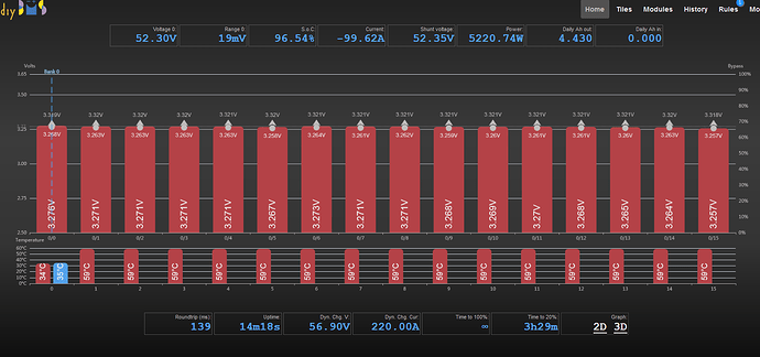
why is the module temperature of the first cell so low?
on the controller dispay it shows low 59 high 59, all fine
have just tested the thermals with all cells on bypass and 500ma current
There are 3 “internal” temperature sensors, one on the V4.9 PCB, and then two on the balance board.
The highest of those 3 is used to determine if an over temperature situation is occuring.
Do you not have any external temperature sensors?


