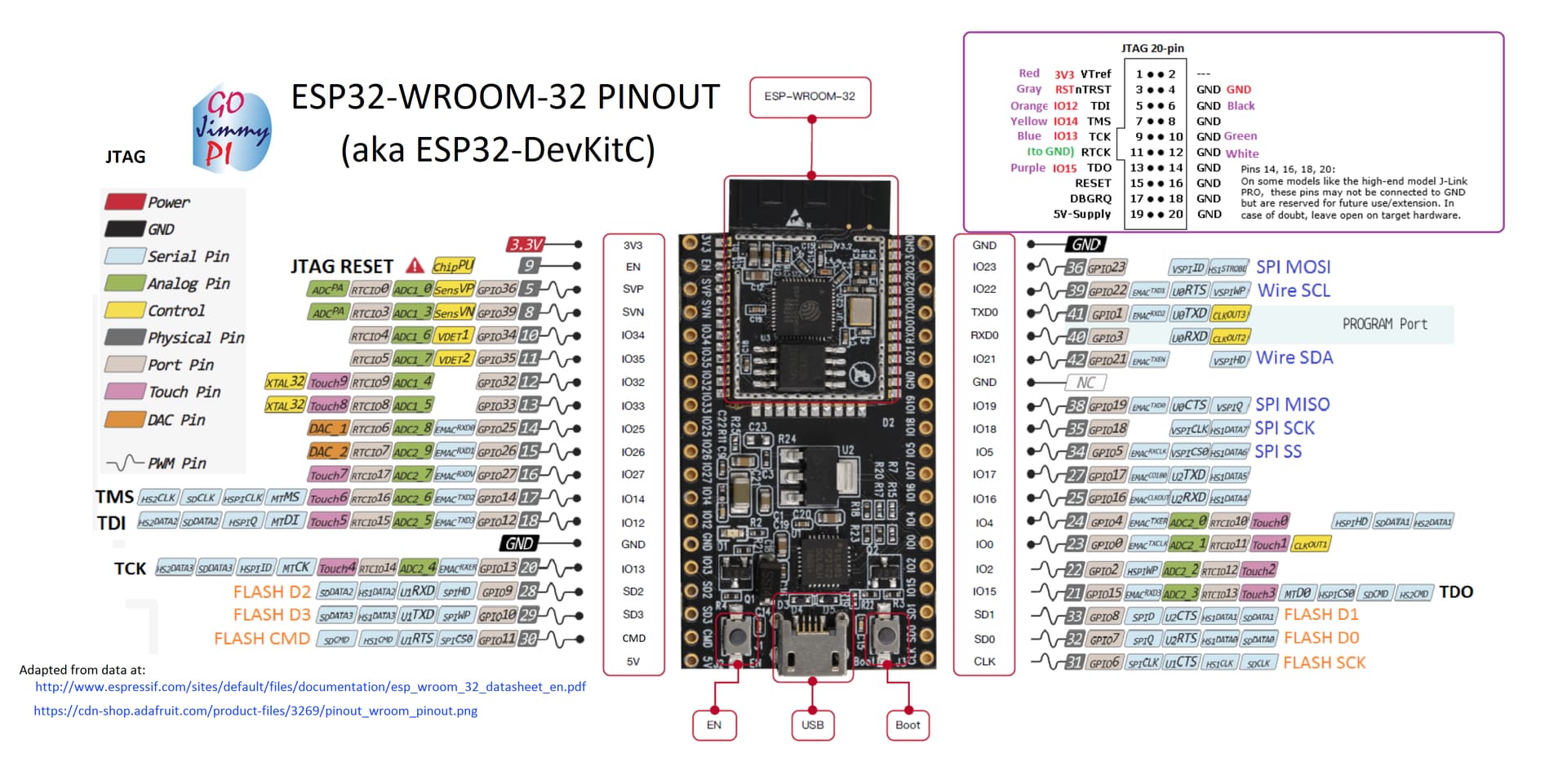
Hi @Tim_Kelley you need the ESP32 thats got the same footprint as the “DEVKIT-C” layout - these may be more suitable Amazon link
Thanks as always, Stuart.
I’m still a beginner with C++ and I2C Comm.
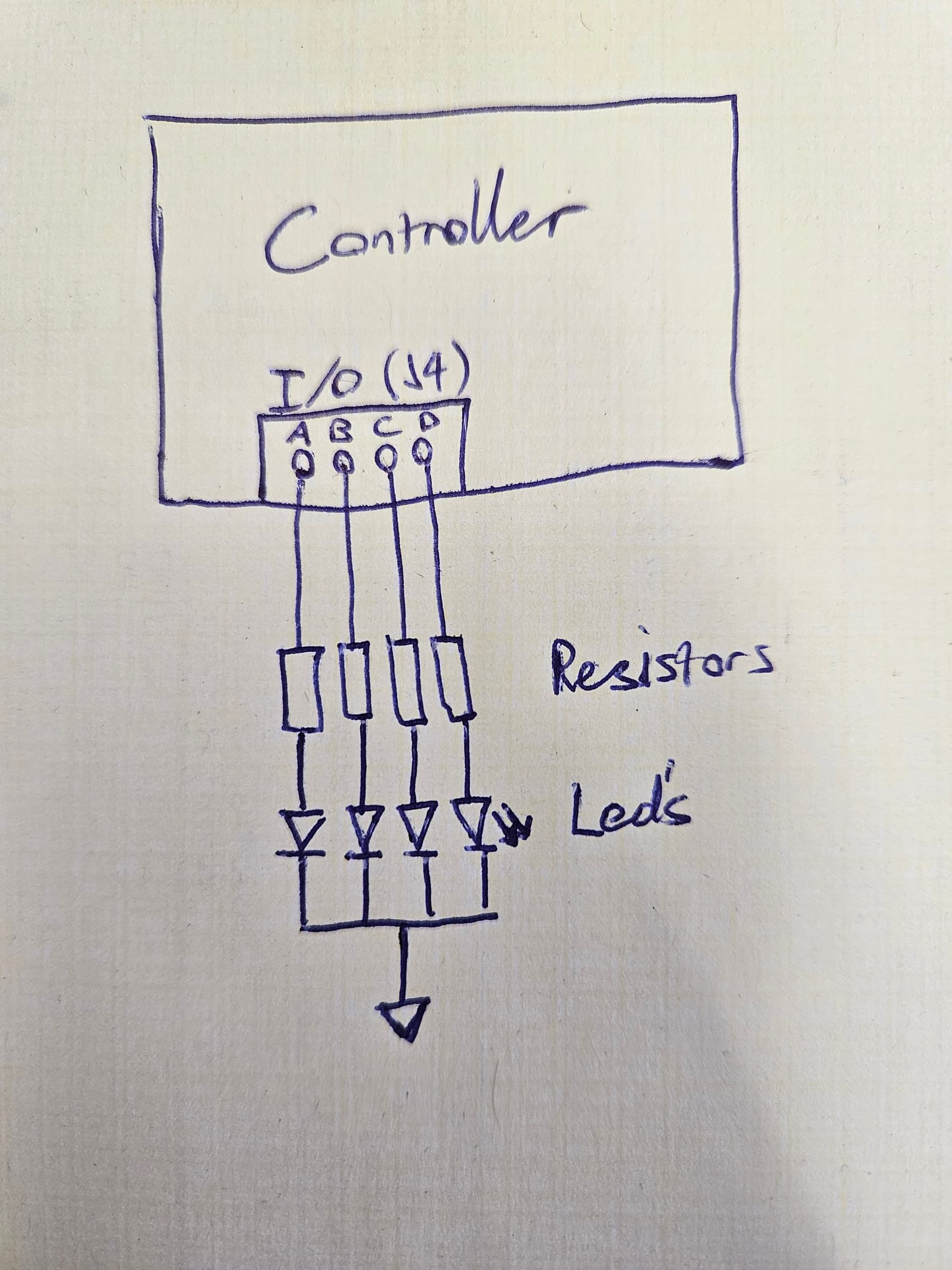
I’m trying to define the I/O pins (J4: A,B,C,D) of the controller as outputs and switch them on and off according to my specifications. I want to use them to control 4 LEDs that show the current State of Charge of the battery and if the battery is charging (used as a powerbank without display).
The I/O pins are controlled by the IC “TCA6416”. I found out through the datasheet how the pins are configured and driven.
Configuration
Excerpt from HAL_ESP32.h
// byte 1   * byte 2
// P7 to P0 * P17 to P10
// 00000000 * 11010000
//  P17, 16 and 14 are inputs
//  i2c output is written as low byte, high byte
#define TCA6416_INPUTMASK 0xD000
Excerpt from HAL_ESP32.cpp
// Set configuration
        ESP_ERROR_CHECK(write16bitWord(I2C_NUM_0, TCA6416_ADDRESS, TCA6416_CONFIGURATION, TCA6416_INPUTMASK));
So the I/O Pins schould already been set as outputs.
The following function should control the output states of the TCA6416
void HAL_ESP32::WriteTCA6416OutputState()
{
    // Emulate the 9534 + 6408 and set the state on the 16 bit output
    TCA6416_Output_Pins = ((uint16_t)TCA9534APWR_Output_Pins << 8) | TCA6408_Output_Pins;
    ESP_ERROR_CHECK_WITHOUT_ABORT(write16bitWord(I2C_NUM_0, TCA6416_ADDRESS, TCA6416_OUTPUT, TCA6416_Output_Pins));
As I understood it, you should be able to switch the desired output on / off with this function call without influencing the relays.
    TCA6416_Output_Pins = 0x000F; //SET P0-P3 to HIGH
        WriteTCA6416OutputState();
        // P0=EXT_IO_A
        // P1=EXT_IO_B
        // P2=EXT_IO_C
        // P3=EXT_IO_D
My idea was to include the function WriteTCA6416OutputState() in HAL_ESP32.h and to make the variable “TCA6416_Output_Pins” public instead of private. Then I want to execute the function in main.cpp.
But does not work like this yet. Does anyone have a tip how to control the four I/O pins in Main.cpp?
Controller Hardware: Latest version with ESP32
Firmware Version: 2023-09-12-10-49
Program used: Visual Studio Code with PlatformIO
Hi Guys,
since I’m gonna build more battery packs I was about to order the AIO-Boards.
Right now there aren’t any U2 and U3 Chips in stock at JLC. How is your experience with those chips.
Should I wait for them to come back in stock or order the ~15 Boards and just solder them to the board?
Thanks in advance,
Max.
Depends on how good your soldering is - I’ve manually built a board from scratch, and its not fun.
U3 has very small pin spacing - you can also use MCP33151-10 instead of the MCP33151-05-E/MS if they have that in stock.
As the ESP32 uses a real time operating system (RTOS) care has to be taken over things occurring in parallel (multi-core cpu). Therefore, writes to i2c devices like the TCA6416 are all pushed through a single task in the code. You would need to look how that works now - for example, its used to drive the flashes of the LED and the relay outputs.
Hello together,
maybe somone has an idear what the problem is.
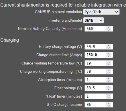
I have a 15s200p battery made of Panasonic NCR18650B cels and a DEYE 12k inverter.
I set the inverter to Lithium mode and Protocol 00
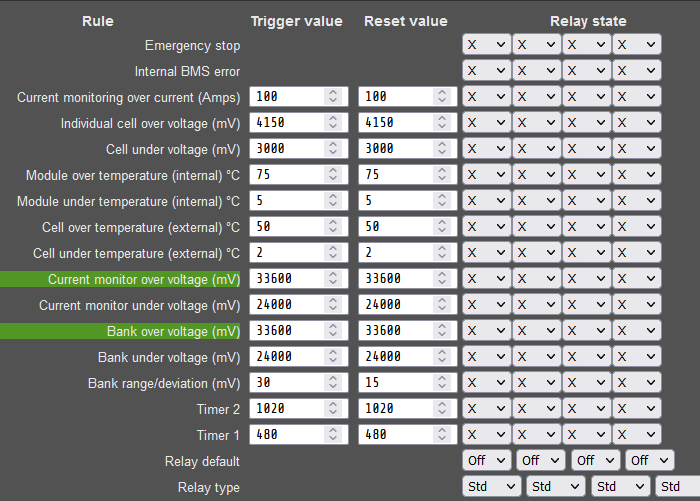
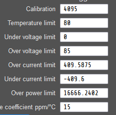
In the DiYBMS i have this settings
The problem is that the inverter doesnot charge the battery, the BMS say that charging is prevented
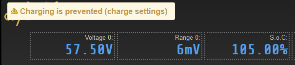
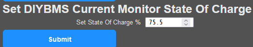
The interresting thing is that the BMS say that the SOC is 105%.
If I want to overwrite this with
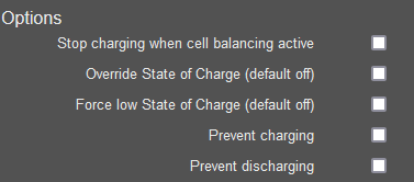
or
nothing happens.
I also cant reset the counters by the way
Many thanks
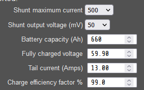
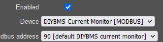
Resetting counter- are you using the external current shunt? If so, update the firmware on that to latest.
Do you have any rules that are active - they also prevent charge such as low cell or high cell voltage etc.
@stuart
Yes i use your external shunt and it should be the latest firmware
There are no rules aktive
Shunt values:
Hello everyone ! This is my first post, because with my Telegram friends we haven’t been able to identify where the problem comes from: I installed a new controller with the new All-in-modules, but the controller keeps rebooting all the time. From the log (connecting though COM) I get the following (sorry can’t attach the txt file yet) when I shut off and restart :
Guru Meditation Error: Core 0 panic’ed (Unhandled debug exception).
Debug exception reason: Stack canary watchpoint triggered (tftupd)
Core 0 register dump:
PC : 0x4008e500 PS : 0x00060936 A0 : 0x4008552a A1 : 0x3ffb4610
A2 : 0x00000009 A3 : 0x0000000b A4 : 0xffffffff A5 : 0x00000000
A6 : 0x3ffb46e0 A7 : 0x00000000 A8 : 0x00000001 A9 : 0x3ffb46e0
A10 : 0x0000005a A11 : 0x0000002a A12 : 0x00000064 A13 : 0x3f4835f8
A14 : 0x00ff0000 A15 : 0xff000000 SAR : 0x0000000c EXCCAUSE: 0x00000001
EXCVADDR: 0x00000000 LBEG : 0x4008ace9 LEND : 0x4008acf9 LCOUNT : 0xfffffff6
Backtrace: 0x4008e4fd:0x3ffb4610 0x40085527:0x3ffb49e0 0x4019f92a:0x3ffb4a70 0x400d715c:0x3ffb4ab0 0x400e53f5:0x3ffb4b20 0x400e5588:0x3ffb4ba0 0x400e5da7:0x3ffb4c20 0x400e610c:0x3ffb4d70
ELF file SHA256: 4a9427f9c4320b96
Guru Meditation Error: Core 0 panic’ed (LoadStoreAlignment). Exception was unhandled.
Core 0 register dump:
PC : 0x4008e8d9 PS : 0x00060034 A0 : 0x80103008 A1 : 0x3ffc8270
A2 : 0x00000013 A3 : 0x4008552a A4 : 0x3ffb4550 A5 : 0x0000024c
A6 : 0x00000008 A7 : 0x3ffc8448 A8 : 0x8008e939 A9 : 0x3ffc8250
A10 : 0x3ffb4558 A11 : 0x3f4699c4 A12 : 0x000000ff A13 : 0x0000ff00
A14 : 0x00ff0000 A15 : 0xff000000 SAR : 0x00000018 EXCCAUSE: 0x00000009
EXCVADDR: 0x40085536 LBEG : 0x4008bb7d LEND : 0x4008bb8d LCOUNT : 0xfffffffe
Backtrace: 0x4008e8d6:0x3ffc8270 0x40103005:0x3ffc82b0 0x40103cb7:0x3ffc82d0 0x401040ee:0x3ffc8360 0x40102fa7:0x3ffc8390
ELF file SHA256: 4a9427f9c4320b96
Re-entered core dump! Exception happened during core dump!
Rebooting…
ets Jun 8 2016 00:22:57
your soc charge resume is on 96% and your curent soc is at 105%
i think this is why it dont allow charging
btw. why you are not using dynamic charging function? this ist very usefull
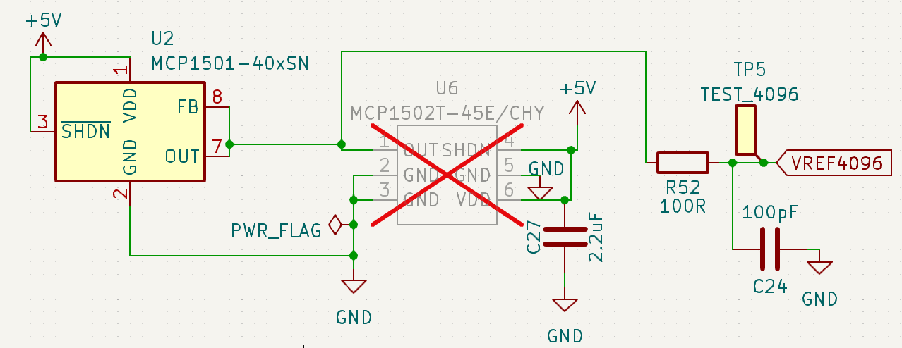
In the 16s module readme you mention U2 and U6. There is no U6 right? You meant to say:
The PCB design has options for two voltage ranges, determined by U2 (“MCP1501-40E/SN” or MCP1502T-45E/CHY).
ONLY ONE OF THESE CHIPS MUST BE FITTED
There are two rules active - both marked in GREEN - those will stop the charging/discharge
This seems to be a problem with a particular variant of the ESP32 - for now, remove the TFT display and it should boot up.
Can you raise a GITHUB issue for this please.
Wrong! U6 is not “normally” fitted - you either install U2 or U6 not both - they have a different footprint, hence the requirement for two parts on the board.
1 Like
i understand it’s not on the bom or ibom but it’s on the board
Hi all, I am getting an error after writing the controller firmware to the esp32 and rebooting. I have used different cables (but the same PC) and even different releases of diyBMS. No luck. I purchased the following:
https://www.amazon.com/dp/B08M5Q1DZF?psc=1&ref=ppx_yo2ov_dt_b_product_details
and
https://www.amazon.com/dp/B08HMJ1X6W?ref=ppx_yo2ov_dt_b_product_details&th=1
Programming finishes fine both connected and disconnected from the controller. Any suggestions on a next troubleshooting step?
I am running on the assumption that my esp32s have hardware that isn’t compatible with the controller (“TCA6416A Not Fitted” and “TCA9534APWR Error”) and have to take another shot at buy more esp32. Please tell me I am wrong.
rst:0x1 (POWERON_RESET),boot:0x13 (SPI_FAST_FLASH_BOOT)
configsip: 0, SPIWP:0xee
clk_drv:0x00,q_drv:0x00,d_drv:0x00,cs0_drv:0x00,hd_drv:0x00,wp_drv:0x00
mode:DOUT, clock div:2
load:0x3fff0030,len:1184
load:0x40078000,len:13232
load:0x40080400,len:3028
entry 0x400805e4
[     9][D][esp32-hal-cpu.c:244] setCpuFrequencyMhz(): PLL: 480 / 2 = 240 Mhz, APB: 80000000 Hz
I (11) diybms:


               _          __
  _|  o       |_)  |\/|  (_
 (_|  |  \/   |_)  |  |  __)
         /

CONTROLLER - ver:f84cc2a2f9a3ea756f9cbde6715fa673f44f21ed compiled 2023-10-14T16:18:00.640Z
ESP32 Chip model = 1, Rev 3, Cores=2, Features=50
I (28) diybms-hal: Configure I2C
I (30) diybms-hal: Scanning i2c bus
I (44) diybms-hal: TCA6416A not fitted, assume v4.2 board
E (45) diybms-hal: TCA9534APWR Error
E (45) diybms-hal: SYSTEM HALTED
ESP_ERROR_CHECK_WITHOUT_ABORT failed: esp_err_t 0xffffffff (ESP_FAIL) at 0x4008e4bb
file: "src/HAL_ESP32.cpp" line 173
func: esp_err_t HAL_ESP32::writeByte(i2c_port_t, uint8_t, uint8_t, uint8_t)
expression: i2c_master_cmd_begin(i2c_num, cmd, pdMS_TO_TICKS(100))
ESP_ERROR_CHECK_WITHOUT_ABORT failed: esp_err_t 0xffffffff (ESP_FAIL) at 0x4008e4bb
file: "src/HAL_ESP32.cpp" line 242
func: void HAL_ESP32::WriteTCA9534APWROutputState()
Hi Tim, has the controller board ever worked (with any ESP?) it could be a bad TCA chip or poor soldering?
Check the pins on the ESP32 to ensure they match the footprint like below…
I get the same error when I am in putty without being connected to the board, One of my ESP32s worked with my old v4.2 controller before I made smoke, so I cannot confirm that it still works, but I can confirm that none of the batches (4+3) that I ordered work with any of the 5 4.6 boards I have. I soldered SW1 and SW2 on - I am not sure what they are for, but I since I had the iron out, I figured why not? I have also jumped JP1. I am booting w/o an SD Card, and both with and without a TFT.
I was able to get some nonstandard (narrower) esp32s to work with the board for a time, but the TFTs cause them to go into a boot loop. My best guess is something is soldered on backwards or the wrong part, that is causing the ESP32s to die. Without a known good, is difficult to troubleshoot. Any suggestions are welcome.